Auxiliary switch for circuit breaker

A technology for auxiliary switches and circuit breakers, applied in the direction of protection switch operation/release mechanism, etc., can solve the problems of processing cost, service life and reliability adverse effects, large elastic deformation of components, large internal stress, etc., to improve the reliability of operation The effect of safety, simple switch structure, and service life protection

Active Publication Date: 2011-01-12
CHANGSHU SWITCHGEAR MFG CO LTD (FORMER CHANGSHU SWITCHGEAR PLANT)
View PDF2 Cites 1 Cited by
  • Summary
  • Abstract
  • Description
  • Claims
  • Application Information

AI Technical Summary

Problems solved by technology

[0007] The disadvantages of the circuit breaker auxiliary switch with the above structure are: the push rod of the micro switch is in the pushed state for a long time, and the internal stress is relatively large, which affects the service life of the micro switch; The elastic reset force of the push rod causes a large force on the housing and transmission parts of the auxiliary switch of the circuit breaker, which requires strict structural strength, and due to the large elastic deformation of the components, it has great impact on the processing cost, service life and reliability. Sex can have adverse effects
The contact of the micro switch is the contact pin of the micro switch. The contact pin of the micro switch is in the ejected state in the reset state through the return spring, which solves the above problems, but the structure is relatively complicated.

Method used


Image

  • Auxiliary switch for circuit breaker
  • Auxiliary switch for circuit breaker
  • Auxiliary switch for circuit breaker

Examples


Embodiment Construction

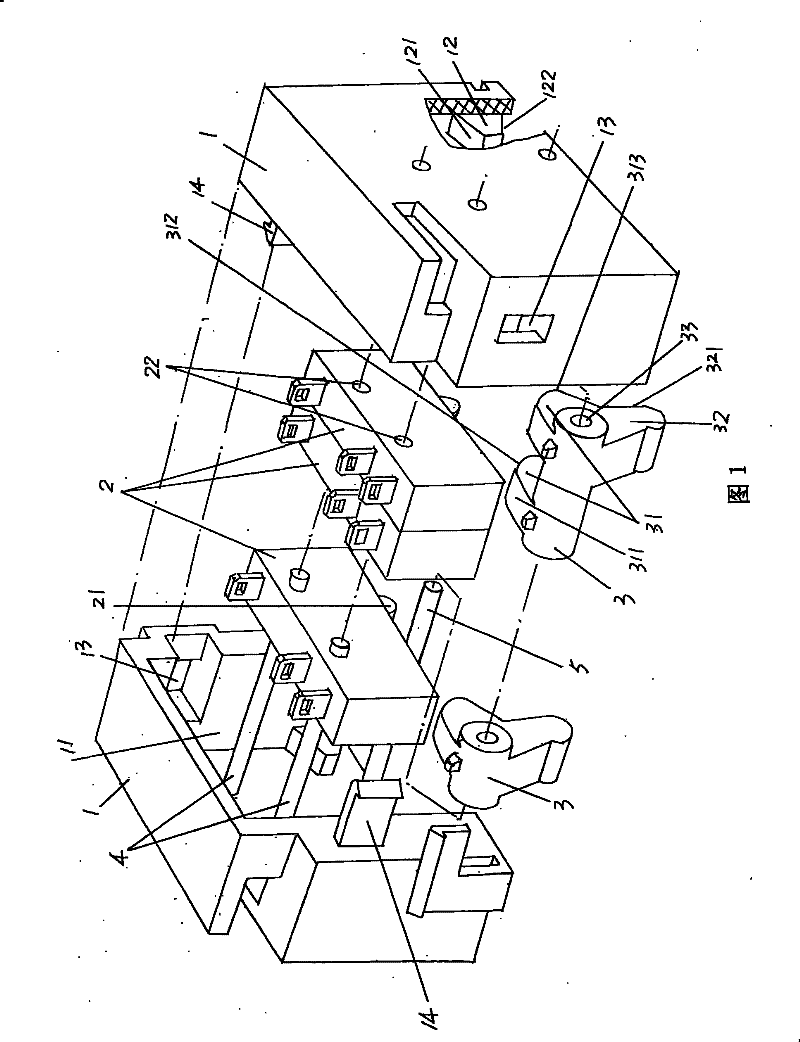
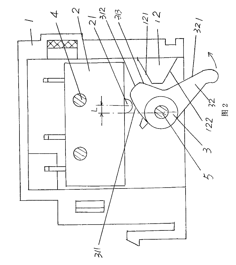
[0024] Please see figure 1 The circuit breaker auxiliary switch recommended in this embodiment includes: a pair of mutually matched housings 1, a micro switch 2 arranged in the housing cavity 11 of the housing 1, and similarly arranged in the housing cavity 11 of the housing 1. The transmission parts 3. The specific shape of the pair of shells 1 is not restricted by the shape shown in the figure. The bottoms of the pair of shells 1 are open, that is, not closed. A tenon hole 13 is provided on one wall in the length direction of each of the pair of shells 1, and a tenon 14 is formed on the other wall in the length direction. The tenon hole 13 described here is essentially a fitting hole, and The tenon 14 described is essentially an embedded foot. The applicant’s previous concept of the opposite directions of the tenon holes 13 and the tenon 14 on the two shells 1 means that the positions of the tenon holes 13 on a pair of shells 1 are opposite to each other, and the positions ...


PUM


Abstract

The invention provides a circuit breaker auxiliary switch, which belongs to the technical field of low-voltage electrical appliance accessories. The auxiliary switch comprises a pair of mutually matched shells, a microswitch arranged in a shell cavity of the shells and a transmission part which is also arranged in the shell cavity of the shells. A first contact arm which is used for actuating a contact pin of the microswitch and a second contact arm which protrudes out of the shells and is used for actuating an operating mechanism of the circuit breaker are formed on the transmission part. The auxiliary switch is characterized in that a first working surface and a second working surface which are used for continuously touching the contact pin of the microswitch are formed on the first contact arm, wherein the first working surface is formed on the upper end face of the first contact arm, and the second working surface is formed on the top end face of the first contact arm. The auxiliary switch has the advantages that the auxiliary switch is favorable for protecting the life span of the microswitch, and can improve the action reliability and safety of the microswitch, so that the reliability of the auxiliary switch can be guaranteed; and the switch is concise in structure and easy to assemble.

Description

Technical field [0001] The invention belongs to the technical field of low-voltage electrical accessories, and in particular relates to a circuit breaker auxiliary switch. Background technique [0002] The circuit breaker usually needs to be equipped with an auxiliary switch. The function of the auxiliary switch is to respond to the action of the circuit breaker operating mechanism and change its on-off state to provide an electrical indication signal of the operating state of the circuit breaker. [0003] The aforementioned auxiliary switches usually include at least one micro switch. The micro switch has a push rod that can be elastically reset. When the push rod is pushed by an external force, the on-off state of the micro switch changes. When the external force is removed, the push rod is reset and automatically ejected, and the on-off of the micro switch is restored to the reset state. [0004] In addition to the micro switch, the auxiliary switch usually includes a spring and ...

Claims


Application Information

Patent Timeline
Patent Type & Authority Patents(China)
IPC IPC(8): H01H71/46
Inventor 顾建青王云峰刘洪武管瑞良
Owner CHANGSHU SWITCHGEAR MFG CO LTD (FORMER CHANGSHU SWITCHGEAR PLANT)
Why Eureka
Try Eureka