Heat exchanger

A technology of heat exchangers and fins, applied in heat exchange equipment, heat exchanger types, indirect heat exchangers, etc., can solve the problem of small temperature difference, difficult heat exchange, and difficult heat exchange between air intake and cooling air And other issues

Inactive Publication Date: 2009-05-27
DENSO CORP
View PDF1 Cites 12 Cited by
  • Summary
  • Abstract
  • Description
  • Claims
  • Application Information

AI Technical Summary

Problems solved by technology

In this way, the temperature difference between the intake air and the cooling air becomes smaller on the intake outlet side, so it may be difficult to perform heat exchange between the intake air and the cooling air
At this time, using the above-mentioned inner fins having the same specifications from the air intake inlet side of the duct to the air intake outlet side will make it difficult to effectively achieve heat exchange on the air intake outlet side of the duct

Method used


Image

  • Heat exchanger
  • Heat exchanger
  • Heat exchanger

Examples


no. 1 example

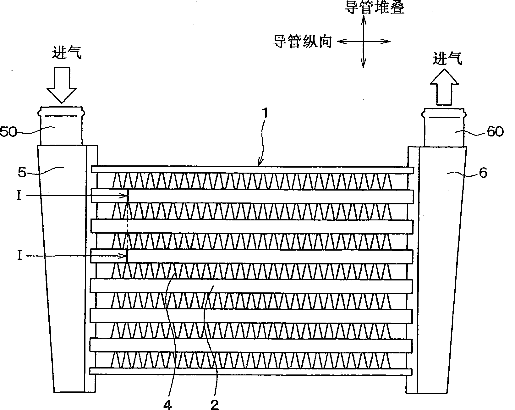
[0029] refer to Figure 1 ~ Figure 4 A first embodiment of the present invention is described below. The heat exchanger according to the first embodiment of the present invention is typically used for an intercooler. The intercooler is configured to perform heat exchange between outside air (cooling air) and intake air for combustion to be input into the internal combustion engine, thereby cooling the intake air. The intake air is an example of the first fluid of the present invention, and cooling air is an example of the second fluid of the present invention.

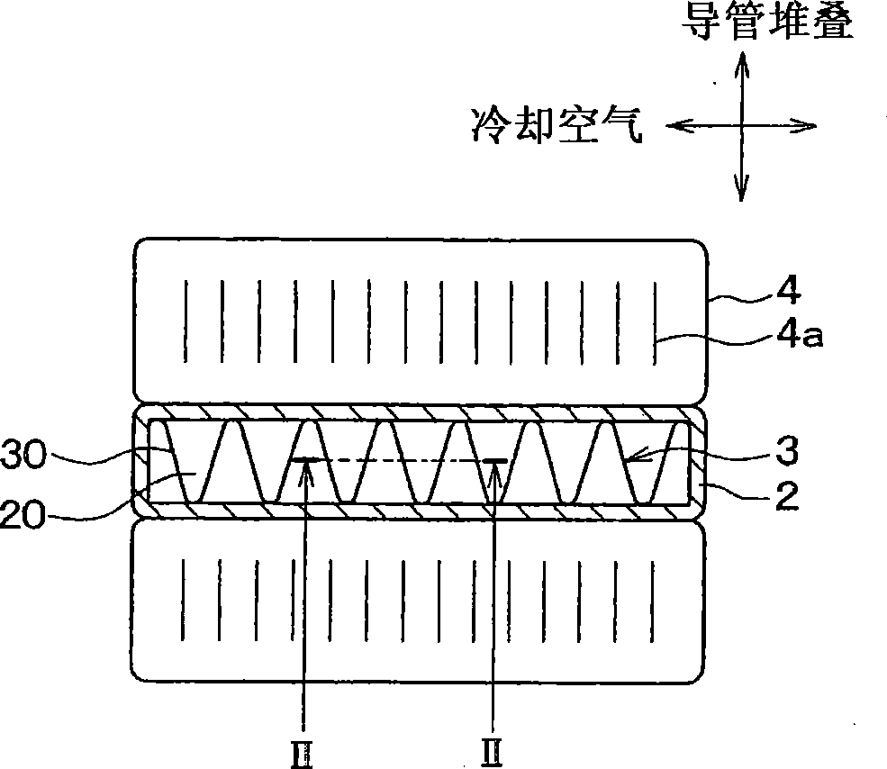
[0030] Such as figure 1 with figure 2 As shown, the core portion 1 of the intercooler includes: a plurality of stacked flat ducts 2, each duct having a flow channel formed inside to allow intake air to flow therethrough; inner fins 3, the inner fins 3 Located inside the flat ducts 2 ; outer fins 4 , each of which is located between stacked flat ducts 2 . The flat ducts 2 are stacked in the duct stacking directio...

no. 2 example

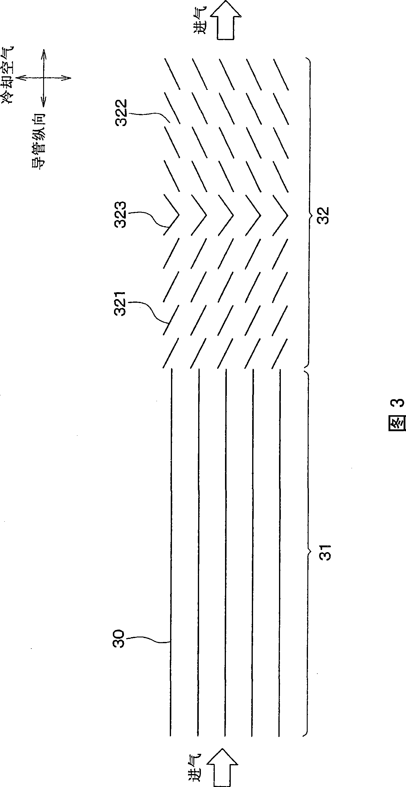
[0047] The second embodiment of the present invention will be shown in Fig. 5 and Figure 6 Based on this, the following description is made. The same components as those of the first embodiment are denoted by the same reference numerals, and descriptions thereof will be omitted below. Fig. 5 shows a cross-sectional view of the inner fin 3 of the second embodiment, when viewed from the stacking direction of the ducts 2 . FIG. 5 of the second embodiment is a view corresponding to FIG. 3 .

[0048] As shown in FIG. 5 , the inner fin 3 of this embodiment includes three different fin portions 31 - 33 . The three fin portions 31 to 33 , namely, the first fin portion 31 , the third fin portion 33 and the second fin portion 32 are successively arranged in the above order from the upstream side of the intake airflow. The first fin portion 31 is a straight fin, similar to the first embodiment. The second flap portion 32 is a strip flap, similar to the first embodiment.

[0049] ...

no. 3 example

[0054] A third embodiment of the present invention will be described below on the basis of FIG. 7 . The same components as those of the first embodiment are denoted by the same reference numerals, and descriptions thereof will be omitted below. Fig. 7 shows a cross-sectional view of the inner fin 3 of the third embodiment, when viewed from the stacking direction of the ducts 2 . The graph shown in FIG. 7 corresponds to the graph of FIG. 3 .

[0055] As shown in Fig. 7, the inner fin 3 of the present embodiment comprises a second two first fin parts 31 and a second fin part 32, and each of said first fin parts is similar to that of the first embodiment. straight fins, and the second fin part is a strip fin similar to the first embodiment. The two first fin portions 31 are arranged one after the other on the upstream side and the downstream side of the second fin portion 32 in the flow direction of the intake air. In other words, the second fin portion 32 is arranged between ...


PUM


Abstract

The invention discloses a heat exchanger, in which a tube is adapted to exchange heat between a first fluid flowing therein and a second fluid flowing through outside of the tube, and an inner fin is disposed in the tube to divide a flow passage in the tube into a plurality of flow paths. The inner fin includes a plurality of fin portions with different specifications, and the fin portions are arranged in series with respect to a flow direction of the first fluid. Furthermore, the fin portion with the smallest flowing resistance of the first fluid among the plurality of fin portions is arranged on an upstream side of the flow direction of the first fluid with respect to at least an another fin portion. Accordingly, heat exchange performance in the entire heat exchanger can be effectively improved.

Description

technical field [0001] The present invention relates to a heat exchanger. The heat exchanger can be adapted to be used as an intercooler, for example, for cooling the intake air to be supplied to the internal combustion engine. Background technique [0002] Conventionally, a heat exchanger such as an intercooler performs heat exchange between cooling air and intake air to be sucked into the internal combustion engine, thereby cooling the intake air (for example, JP-A-2006-90305). The intercooler includes inner fins inserted into ducts in which air flows, which promotes heat exchange between intake air and cooling air. The inner fins generally have the same shape, ie the same gauge from the air intake inlet side to the air intake outlet side of the duct within the intercooler. [0003] According to experiments conducted by the inventors of the present application, Figure 8 The relationship between the intake air temperature Tg in the duct and the distance H from the intake...

Claims


Application Information

Patent Timeline
Patent Type & Authority Applications(China)
IPC IPC(8): F28D7/00F02B29/04
CPCF28D1/05366F28D2021/0082F28F1/128F28F1/40
Inventor 原田真树须佐澄男渡边晴彦
Owner DENSO CORP
Why Eureka
Try Eureka