

Portable vegetation coverage measuring instrument
A technology of vegetation coverage and measuring instrument, which is applied in the direction of measuring devices, instruments, and optical devices, can solve the problems of not being able to guarantee the level of camera shooting status, and achieve the effect of extracting vegetation coverage, scientific conception, and simple structure
- Summary
- Abstract
- Description
- Claims
- Application Information
AI Technical Summary
Problems solved by technology
Method used
Image


Examples
Embodiment Construction
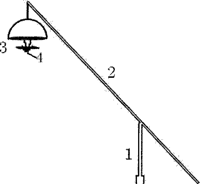
[0028] See figure 1 , figure 2 , image 3 , Figure 4 , Figure 5 , Figure 6 , Figure 7 As shown, a portable vegetation coverage measuring instrument is composed of a support pole 1, a main pole 2, a camera platform 3 and a digital camera 4. ( figure 1 )
[0029] The support rod 1 ( figure 2 ) is a section of steel pipe on the top, and two spiked forks below, which are used to fix the instrument on the ground, and the two spikes below are easy to insert into the ground to keep the stability of the field instrument.
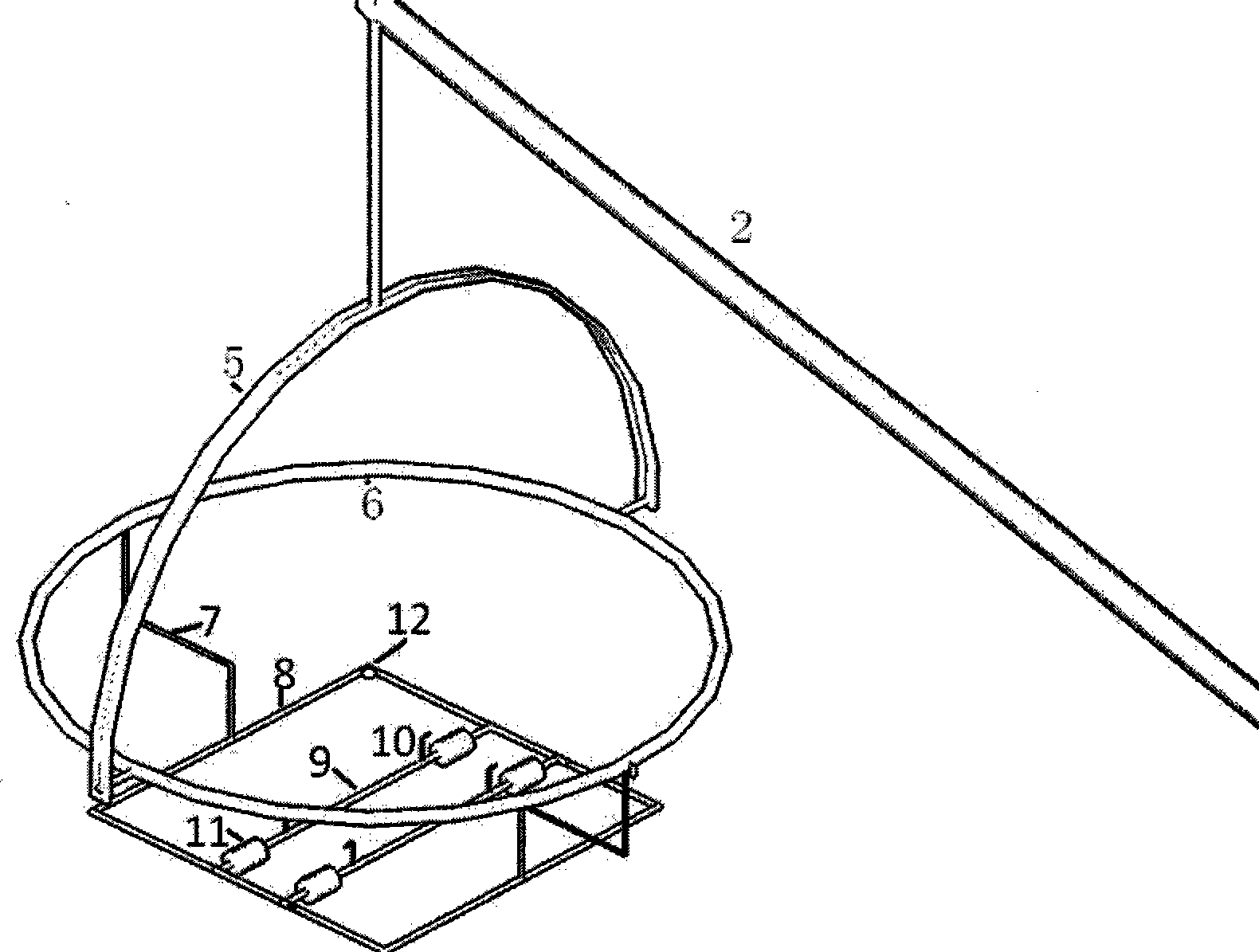
[0030] The main pole 2 is also a steel pipe, which is used to raise the camera platform 3 to a certain height. According to the difference of ground features, the main pole 2 can be extended. The main rod 2 and the supporting rod 1 are connected by pin shafts.
[0031] The camera platform 3 ( image 3 ) adopts the principle of the cloud platform, and is composed of a downward semicircular ring 5, a horizontal circular ring 6 and a horizontal square...
PUM
 Abstract
Description
Claims
Application Information