Phase change memory device for multibit storage

A phase-change storage and equipment technology, applied in information storage, static memory, read-only memory, etc., can solve problems such as weakening time and temperature stability, the impact of intermediate-level readability, and difficulties

Active Publication Date: 2009-05-27
STMICROELECTRONICS SRL +1
View PDF2 Cites 1 Cited by
  • Summary
  • Abstract
  • Description
  • Claims
  • Application Information

AI Technical Summary

Problems solved by technology

It was thus concluded that, due to the generally observed time-dependent resistivity change of the amorphous portion directly affecting the resistance of the cell, there is an...

Method used


Image

  • Phase change memory device for multibit storage
  • Phase change memory device for multibit storage
  • Phase change memory device for multibit storage

Examples


Embodiment Construction

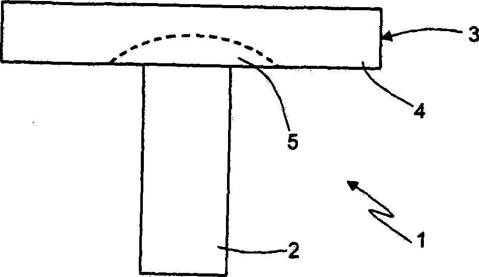
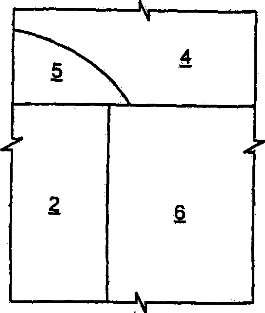
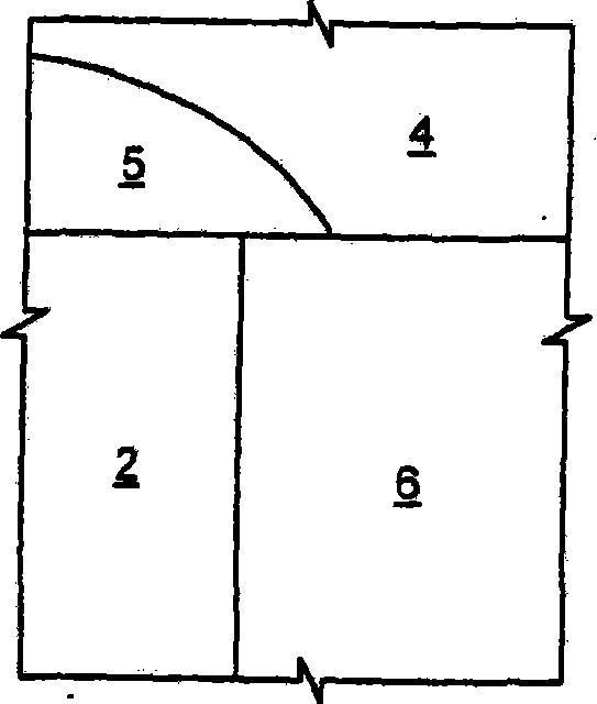
[0025] Figures 3a-3d shows part of PCM device 10, with figure 1 and Figure 2a-2d Similar to the PCM device in , the PCM device 10 includes a heater 2 surrounded by a dielectric layer 6 and covered with a storage device 3 . exist Figures 3a-3d in, with figure 1 and Figure 2a-2d Similar to the case in , the memory device 3 has been programmed in four cases, and the memory device 3 includes a polycrystalline portion 4 and an amorphous portion 5 . Here, the narrow resistive region 11 protrudes from the upper edge of the heater 2 along the surface between the dielectric layer 6 and the storage device 3 . The narrow resistive region 11 is made of a conductive material, such as metal or doped polysilicon, and has a reduced thickness. Preferably, the narrow resistive region 11 is made of the same material as the heater 2, such as TiN, TiAlN, TiSiN. Alternatively, it can also consist of a different material. For example, the heater 2 may be made of TiAlN, while the narrow r...


PUM

PropertyMeasurementUnit
Thicknessaaaaaaaaaa

Abstract

A phase change memory device (10) having a heater element (2) and memory region (3) of chalcogenic material. The memory region has a phase changing portion (5) in electrical and thermal contact with the heater element and forms a first current path between the heater element and a rest portion (4) of the memory element. The phase changing portion (5) has a dimension correlated to information stored in the memory region and a higher resistivity than the rest portion (4). A parallel current path (11) extends between the heater element (2) and the rest portion (4) of said memory element and has a resistance depending upon the dimension of the phase changing portion (5) and lower than the phase changing portion (5), thus modulating the overall resistance of phase change memory device.

Description

technical field [0001] The invention relates to a phase-change storage device for multi-bit storage. Background technique [0002] As we know, phase-change memory devices use phase-change materials. The so-called phase-change materials are for electronic storage applications, which can be electrically switched between a generally amorphous state and a generally crystalline state, or between a completely amorphous state and a completely Materials that switch electrically between different detectable localized ordered states in the full range between crystalline states. The state of the phase change material is also non-volatile, specifically, when setting the indicated resistance value in the crystalline state, semi-crystalline state, amorphous state or semi-amorphous state, since the value represents the phase or physical state (for example, crystalline or amorphous), so the value remains unchanged until changed by another programming event. The state is not affected by re...

Claims


Application Information

Patent Timeline
IPC IPC(8): H01L45/00G11C16/02G11C11/56
CPCG11C13/0004G11C11/5678G11C11/56H01L45/06H01L45/144H01L45/126H01L45/1233H10N70/8413H10N70/231H10N70/8828H10N70/826H10N70/8825
Inventor A·里德艾里F·佩利泽尔A·皮罗瓦诺
Owner STMICROELECTRONICS SRL
Why Eureka
Try Eureka