Multi-stage compressor, air-separating apparatus comprising such a compressor, and installation

An air separation and compressor technology, applied in the field of multi-stage compressors, can solve problems such as efficiency loss and flow rate increase

Inactive Publication Date: 2009-05-27
LAIR LIQUIDE SA POUR LETUDE & LEXPLOITATION DES PROCEDES GEORGES CLAUDE
View PDF0 Cites 9 Cited by
  • Summary
  • Abstract
  • Description
  • Claims
  • Application Information

AI Technical Summary

Problems solved by technology

If it is required to reduce the pressure on the delivery side of each stage, the characteristics of the compressor wheel are such that this will lead to an incre

Method used


Image

  • Multi-stage compressor, air-separating apparatus comprising such a compressor, and installation
  • Multi-stage compressor, air-separating apparatus comprising such a compressor, and installation
  • Multi-stage compressor, air-separating apparatus comprising such a compressor, and installation

Examples


Embodiment Construction

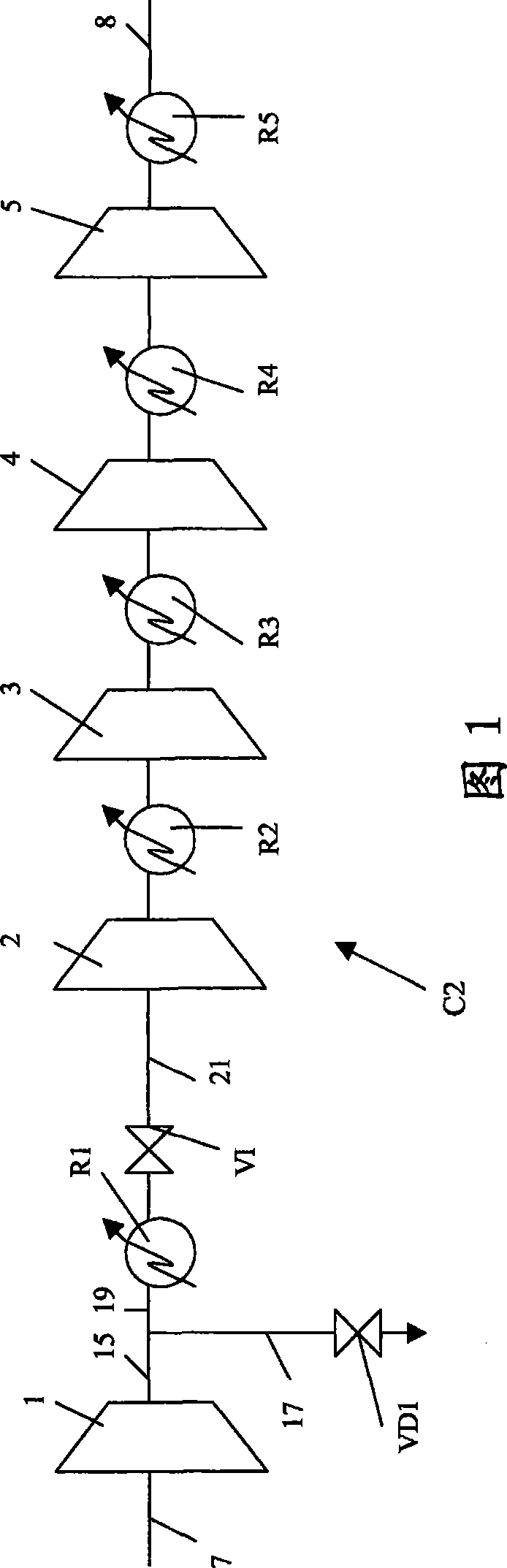
[0025] Figure 1 shows a compressor with five stages 1, 2, 3, 4, 5 on the same axis with cooling means R1, R2, R3, R4, R5 between each stage and downstream of the last stage C2. The air 7 is conveyed to the first stage 1 with flow regulating moving vanes.

[0026] During rated operation, the vanes of stage 1 do not reduce the flow rate, all the air compressed in the first stage 1 enters the ducts 15, 19, 21 and passes throttling valve V1 without reducing the pressure. This flow rate is then compressed in stages 2,3,4,5.

[0027] In reduced flow rate operation, the vanes of the first stage 1 reduce the flow rate of air 7 to 70% of the nominal flow rate. The flow rate of 12.2% of the rated flow rate is discharged to the outside through the pipe 17 and the pressure reducing valve VD1. The remaining air at 57.8% of the rated flow rate is sent to cooler R1 and then to the throttle valve which reduces its pressure to 57.8% of the rated pressure value. This depressurized flow rate...


PUM


Abstract

A compressor comprises a first stage and a second stage (1, 2) which are mounted on a common axis with means for supplying the first stage with a gas that is to be compressed, means for transferring the compressed gas from the delivery side of the first stage to the inlet side of the second stage, means for producing a pressurized gas on the delivery side of the second stage and means for sendingthe compressed gas from the delivery side of the first stage to the inlet of the second stage and a throttle valve (V1) to reduce the pressure of the compressed gas downstream of the delivery side ofthe first stage and upstream of the inlet side of the second stage, means for sending the compressed gas from the delivery side of the first stage to the inlet of the second stage via the throttle valve and means (17, VD1) for sending some of the gas compressed in the first stage to the open air. Application to the production of compressed air for an air separation apparatus.

Description

technical field [0001] The invention relates to a multi-stage compressor, an air separation device and equipment including the compressor. Background technique [0002] In the IGCC power generation process using oxygen in the gasifier, part of the air compressed in the gas turbine compressor can be used to feed an air separation unit (ASU) which supplies oxygen to the gasifier. [0003] This arrangement is used to accommodate the operation of gas turbines, which are generally designed to burn gas with a higher calorific value than that produced by the gasifier. [0004] The air from the gas turbine is usually at a higher pressure than normally used in the ASU. To avoid any loss of power, it is advantageous that this air is used in the ASU at the available pressure. While this air forms only part of the supply to the ASU, the rest of the required air must be compressed in a separate compressor. It is preferred that the second air flow rate is compressed to the same pressur...

Claims


Application Information

Patent Timeline
IPC IPC(8): F04D27/02
CPCF04D27/0207F25J3/04781F25J2240/42F25J3/04575F25J3/04018F04D17/12F25J3/04127F04D27/0269F25J3/04606
Inventor B·达勒多
Owner LAIR LIQUIDE SA POUR LETUDE & LEXPLOITATION DES PROCEDES GEORGES CLAUDE
Why Eureka
Try Eureka