Lens module

A technology for lens module and lens retention, which is applied in installation, optics, television, etc., can solve problems such as complex structure of lens module, uncertain magnetization direction of excitation components, and difficult control of friction force, etc., to achieve automatic focusing and zooming functions, The number of components is simple and reliable, and the effect of less friction joints

Inactive Publication Date: 2009-05-27
TOKIN CORP +1
View PDF1 Cites 4 Cited by
  • Summary
  • Abstract
  • Description
  • Claims
  • Application Information

AI Technical Summary

Problems solved by technology

[0010] Specifically, in the case of the method disclosed in Patent Document 1, a structure for supporting the driving member in a movable manner with respect to the stationary member is necessary, and it is necessary to use an elastic member such as a leaf spring to frictionally couple the driving member and the driven member. Therefore, not only the structure of the lens module becomes complicated, but also the control of the friction force is difficult, so there is a problem that the moving speed of the driven object deviates
[0011] In addition, in the case of the method disclosed in Patent Document 2, the magnetization direction of the excitation member is uncertain. In the magnetic circuit formed by the driving member of the material, since the magnetic flux distribution is asymmetrical up and down, there is a problem that there is a significant difference in the moving speed when the lens is extended and when the lens is retracted.
Therefore, if the above-mentioned known technology is used to realize the autofocus and zoom functions at the same time, there will be a problem that the camera will become more complicated and larger.

Method used


Image

  • Lens module
  • Lens module
  • Lens module

Examples


Embodiment 1

[0061] Figure 5 The basic configuration of the lens module according to Example 1 of the present invention is shown, (a) is an external plan view viewed from the upper surface direction, and (b) is a diagram related to a side sectional view in the direction of line A-A of (a) .

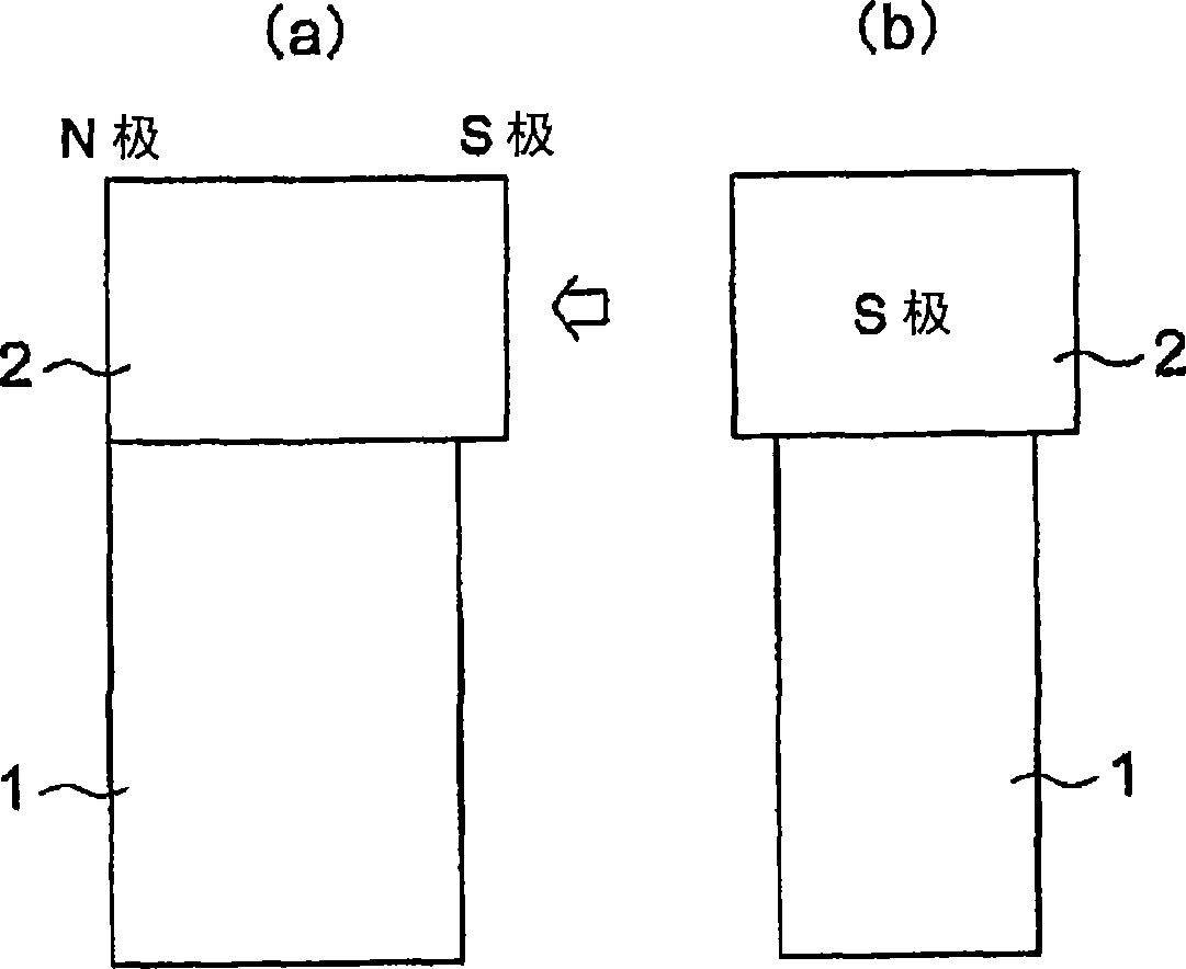
[0062] In this lens module, it is used as a driving body figure 1 The type shown in (a), (b), with respect to the housing 7, the lens holder 6 is installed with the guide pin 8, and the lens holder 6 is installed with a moving member as a moving member made of a material capable of attracting the magnet 4. body 5, and one end face side of the displacement generation direction (longitudinal direction) of the piezoelectric ceramic element 3 made of laminated piezoelectric ceramics is bonded to the magnet 4, and the other end face side is bonded to the magnet 4 as a stationary The casing 7 of the component is made of a material capable of absorbing the magnet 4. The movable body 5 and the magnet 4 as ...

Embodiment 2

[0070] Figure 6 The basic configuration of the lens module according to Example 2 of the present invention is shown, (a) is an external plan view viewed from the upper surface direction, and (b) is a diagram related to a side sectional view in the direction of line BB of (a) .

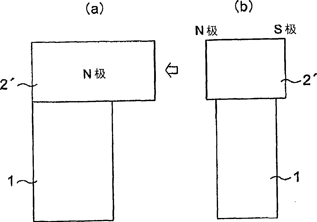
[0071] In this lens module, it is used as a driving body figure 2 The types shown in (a) and (b) are constructed in such a way that the vibration of the housing 7 does not leak out according to the structure of the case of the first embodiment, and are similar to the case of the first embodiment in terms of the basic structure. They are common in that the lens holder 6' is mounted on the housing 7' with the guide pin 8', and the lens holder 6' is equipped with a moving member made of a material capable of attracting to the magnet 4' as a moving member. body 5', and one end face side of the displacement generation direction (longitudinal direction) of the piezoelectric ceramic element 3 made of lami...

Embodiment 3

[0094] Fig. 8 shows the basic structure of the lens module according to Embodiment 3 of the present invention, (a) is a diagram related to the external appearance plan view viewed from the upper surface direction, and the same figure (b) is C— Figures related to the side sectional view in the direction of the C line.

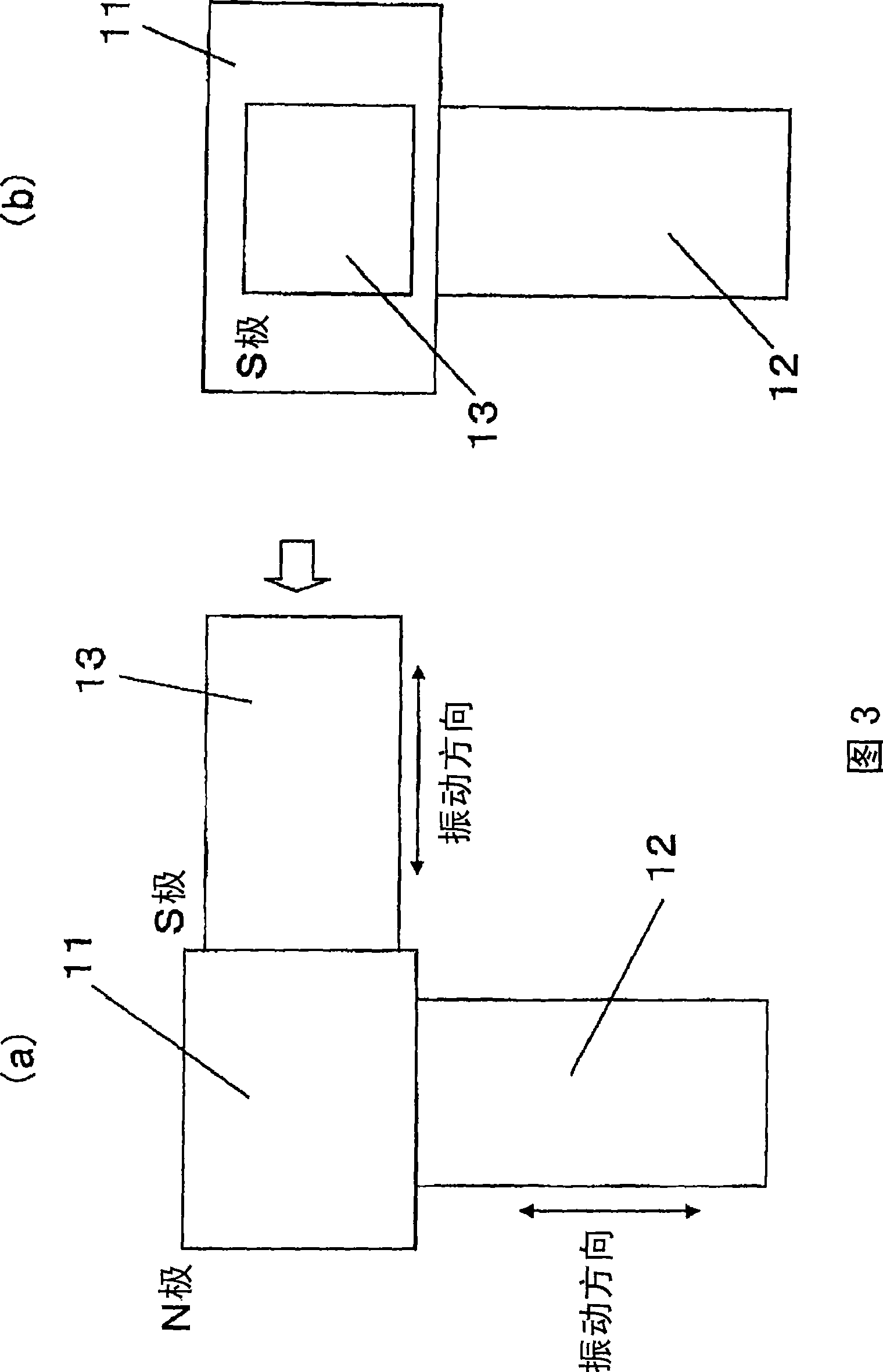
[0095] In this lens module 102, it is used as a driving body Figure 6 The type shown in (a), (b) is equipped with the first lens holder 24 of the moving body 18 as a moving member made of a material capable of attracting to the magnet 19, and with respect to the axial direction of the moving body 18 (and light The second lens holder 23 , which is supported so as to be movably axially rotated by the rotation of the same axis), has a structure that is attracted by the magnetic force of the magnet 19 as in the first and second embodiments.

[0096] Here, one end of the piezoelectric ceramic element 20 is bonded to the case 25 as a stationary member, and the other...


PUM


Abstract

Provided is a lens module having a lens drive mechanism having a simple structure which can stabilize the shift speed of an optical lens. The lens module has a structure wherein a lens holder (6), on which a moving body (5) that can be attracted to a magnet (4) is mounted and the optical lens not shown in a figure is to be mounted, is mounted on a housing (7) by using a guide pin (8), one side of a piezoelectric ceramic element (3) in a displacement generating direction (longitudinal direction) is bonded to the magnet (4), the other side is bonded to the housing (7), and the moving body (5) and the magnet (4) are attracted by a magnetic force. The lens holder (6) supporting the moving body (5) is supported by the guide pin (8) in a manner that the lens holder can be shifted. A lens driving mechanism has the magnetization direction of the magnet (4) in the radius direction of the optical lens by permitting the magnetization direction to substantially orthogonally intersect with the optical axis direction of the optical lens. The lens module is provided with the lens drive mechanism which vibrates the magnet (4) by vibration generated by a piezoelectric ceramic element (3), and shifts the lens holder (6) along an optical axis direction by driving the moving body (5) by using the vibration of the magnet (4) as a driving force.

Description

technical field [0001] The present invention is mainly applicable to a lens module suitable for use in digital video cameras, digital cameras, cameras for mobile phones, etc., and more specifically, relates to an optical device suitable for use in automatic focus and zoom functions, and has a function of moving in a predetermined direction. Lens module for optical lenses. Background technique [0002] Conventionally, in order to provide a camera with autofocus and zoom functions, a mechanism for moving an optical lens along an optical axis is required, and a method using an electromagnetic motor is generally known. [0003] However, in recent years, optical devices represented by digital cameras and camera-equipped mobile phones have been miniaturized rapidly. Along with this, electric / mechanical conversion elements such as piezoelectric elements have been proposed from electromagnetic motors. The technology of the moving method of the optical lens is constantly becoming ma...

Claims


Application Information

Patent Timeline
Patent Type & Authority Applications(China)
IPC IPC(8): H02N2/00G02B7/04G02B7/08
CPCG02B7/102H02N2/025H02N2/0095G02B15/00H04N23/00
Inventor 西宫幸雄相泽周二山崎大辅千叶美帆米泽友浩本多和德高伟
Owner TOKIN CORP
Why Eureka
Try Eureka