Automatic chuck jaw change system in combined machining lathe

A compound processing and automatic replacement technology, which is applied to tool changing devices, chucks, lathes, etc., can solve the problems of insufficient positioning accuracy and mechanical positioning accuracy

Active Publication Date: 2009-06-03
YAMAZAKI MAZAK KK
View PDF3 Cites 7 Cited by
  • Summary
  • Abstract
  • Description
  • Claims
  • Application Information

AI Technical Summary

Problems solved by technology

[0008] The positioning accuracy of the tip of the arm of the robot that carries in and out the workpiece is not sufficient compared with the mechanical positioning accuracy of each device of the multi-function lathe

Method used


Image

  • Automatic chuck jaw change system in combined machining lathe
  • Automatic chuck jaw change system in combined machining lathe
  • Automatic chuck jaw change system in combined machining lathe

Examples


Embodiment Construction

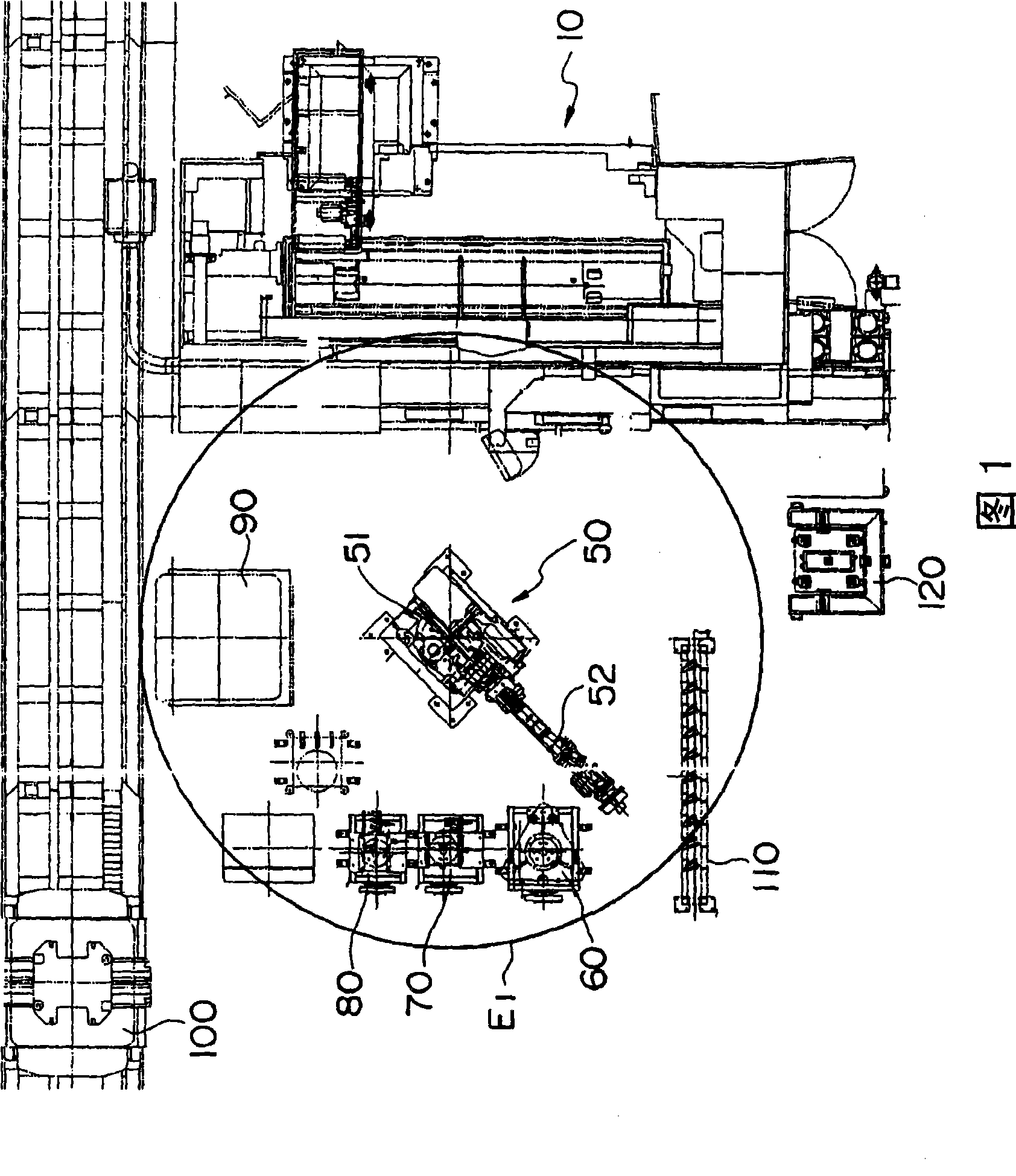
[0029] FIG. 1 is a plan view showing the overall configuration of a chuck jaw replacement system of a combined machining lathe according to the present invention.

[0030] This system has a multi-joint robot 50 equipped in front of a compound machining lathe 10 .

[0031] The robot 50 has a body 51 and an arm 52 extending from the body 51. A workpiece hand 60 for holding a workpiece and a pliers 70 for holding a chuck jaw are selectively installed on the front end of the arm 52 to release the spindle from the compound processing lathe 10. Lock the nut wrench 80 on the chuck. Each hand is placed on its own stage.

[0032] A workpiece supply station 90 , a pallet conveying device 100 for conveying pallets to the workpiece supply station 90 , and the like are installed on the side of the composite machining lathe 10 .

[0033] In addition, a shelf-shaped claw storage room 110 is also arranged.

[0034] The robot 50 is represented by symbol E in FIG. 1 1 The area shown as the ...


PUM


Abstract

In an automatic chuck jaw change system, a combined machining lathe capable of positioning with high precision and a robot with lower positioning precision than the combined machining lathe cooperate to automatically change a chuck jaw. The system includes a robot (50) disposed in front of the combined machining lathe, and the robot (50) can be selectively mounted on a front end of an arm (52) thereof with a work hand for operating a work (60), a chuck jaw (70), and a nut runner hand (80) for operating a drive mechanism of the chuck. The robot cooperates with a tool for jaw mounted on a tool spindle of the combined machining lathe to automatically change a chuck jaw of a main spindle.

Description

technical field [0001] The invention relates to an automatic exchange system for chuck jaws of a compound processing lathe. Background technique [0002] Since the compound machining lathe can process various workpieces, it is necessary to prepare chuck jaws corresponding to the shape and structure of the workpiece. [0003] The following patent documents disclose a chuck jaw replacement system device and the like of a compound machining lathe. [0004] In addition, in order to allow the multi-function lathe to operate unmanned and automatically for a long time, it is necessary to equip the multi-function lathe with a robot that transports workpieces in and out. [0005] Patent Document 1: Japanese Patent Laid-Open No. 6-190616 [0006] Patent Document 2: JP-A-6-143014 Gazette [0007] Patent Document 3: JP-A-61-103746 Gazette [0008] The positioning accuracy of the tip of the arm of the robot that carries in and out the workpiece is insufficient compared with the mecha...

Claims


Application Information

Patent Timeline
Patent Type & Authority Applications(China)
IPC IPC(8): B23B31/39
CPCB23B31/39Y10S483/901Y10S279/901Y10T29/5114Y10T279/34Y10T279/1993Y10T483/1705Y10T483/171Y10T82/2572Y10T483/15
Inventor 寺园信也水谷文哉
Owner YAMAZAKI MAZAK KK
Why Eureka
Try Eureka