
Cutting technique

A technology of cutting process and beam cutting, which is applied in glass cutting devices, manufacturing tools, glass manufacturing equipment, etc., can solve the problems affecting the processing accuracy and yield, and the uneven section of liquid crystal display panel 110, so as to save process time and optimize Effect of cutting cross section and reducing tolerance

Active Publication Date: 2009-06-03
AU OPTRONICS CORP
View PDF0 Cites 9 Cited by
  • Summary
  • Abstract
  • Description
  • Claims
  • Application Information

AI Technical Summary

Problems solved by technology

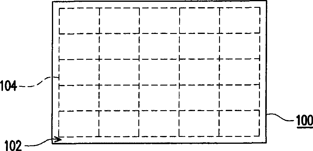
Additionally, due to the use of Figure 1D The illustrated cutter wheel 130 mechanically cuts the finished product 100, so the edge of the obtained liquid crystal display panel 110 is likely to have an uneven section (burr), which in turn affects the processing accuracy and the yield of the subsequent process.

Method used


Image

  • Cutting technique
  • Cutting technique
  • Cutting technique

Examples


Embodiment Construction

[0035] Figure 2A to Figure 2D It is a schematic flow diagram of a cutting process according to an embodiment of the present invention, wherein Figure 2A and Figure 2D is a schematic top view of the cutting process, and Figure 2B and Figure 2C is a three-dimensional schematic diagram of the cutting process. The cutting process of this embodiment is suitable for cutting a workpiece 200, wherein the workpiece 200 may be a finished product, a semi-finished product or a mother sheet of a liquid crystal display panel. This embodiment uses a glass substrate as an example of the workpiece 200, but is not limited thereto. In this embodiment, the workpiece 200 has a plurality of cutting lines 206 designed according to user needs. In the following steps, the workpiece 200 will be cut along the cutting lines 206 with a cutting beam, wherein Figure 2A The illustrated cutting lanes are for illustration purposes only and are not intended to be limiting. The following will describe...


PUM


Abstract

The invention provides a cutting technique suitable for cutting a workpiece. The cutting technique comprises the following steps: at first, an optics membrane is stuck on the surface of the workpiece; then, the surface of the workpiece is cut by a machining tool, so as to form an initial crack on the edge of the workpiece; finally, a cutting beam is supplied by which the workpiece and the optics membrane are cut simultaneously starting from the initial crack. Employing the cutting technique of the invention can not only save the technique time, and reduce the technique cost, but also have a better rate of finished products.

Description

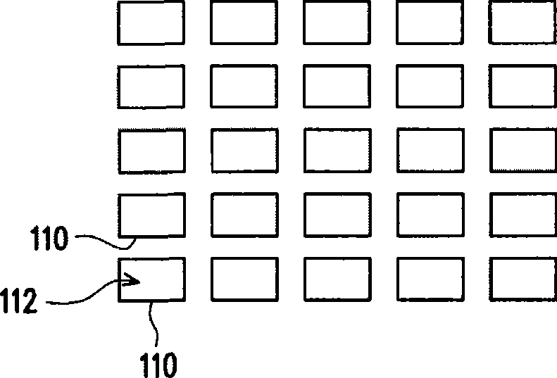
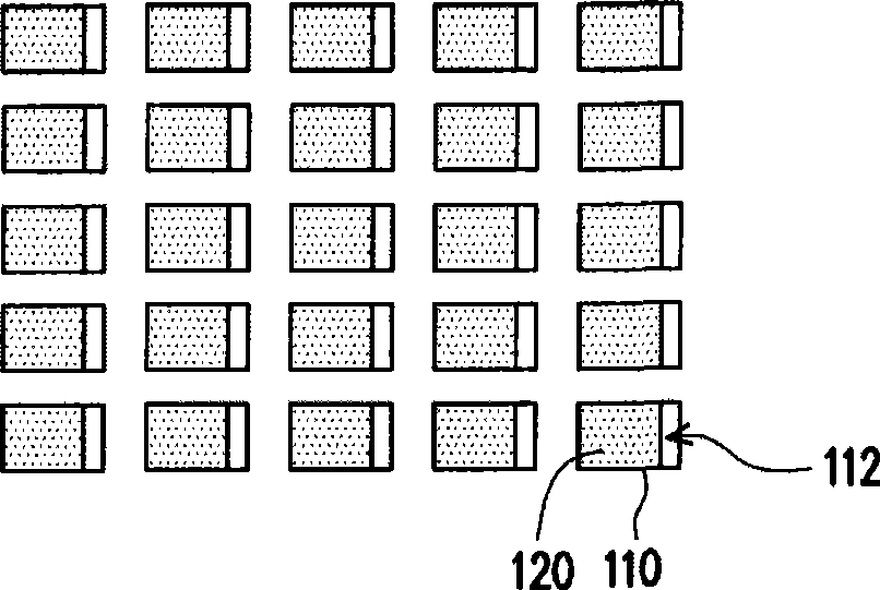
technical field [0001] The present invention relates to a cutting process, and in particular to a cutting process using a cutting beam. Background technique [0002] A liquid crystal display panel is mainly composed of two substrates sandwiching a liquid crystal layer, such as an active element array substrate and a color filter substrate, and the substrates of these substrates are usually made of glass. Therefore, how to improve the yield of these substrates during cutting and molding is very important. [0003] Figure 1A to Figure 1C It is a schematic flow chart of a cutting process for a known liquid crystal display panel, and Figure 1D It is a schematic cross-sectional view of cutting a liquid crystal display panel with a knife wheel. Firstly, a finished product 100 after assembly of an active element array substrate (not shown) and a color filter substrate (not shown) is provided, as shown in Figure 1A shown. Among them, the finished product 100 has multiple stri...

Claims


Application Information

Patent Timeline
IPC IPC(8): C03B33/07
Inventor 许胜允黄慧雯何圣智赖志明陈淑媺
Owner AU OPTRONICS CORP
Learn More