
Control device for flying tension and flying time of weft of air jet loom and control method thereof

A control device and time-of-flight technology, applied to looms, textiles, papermaking, textiles, etc., can solve the problems of reduced traction, restrained weft breakage during flight, increased air consumption, etc., to reduce the level of weft tension and prolong the time , Reduce the effect of weft breaking rate

Active Publication Date: 2009-06-03
WUJIANG WANGONG ELECTROMECHANICAL EQUIP
View PDF1 Cites 18 Cited by
  • Summary
  • Abstract
  • Description
  • Claims
  • Application Information

AI Technical Summary

Problems solved by technology

The weft yarn can be divided into start-up phase, free flight phase and restrained flight phase during the flight process. The air consumption of each phase is substantially different, especially in the weft yarn restrained flight phase, so that the weft yarn can move from a high-speed state in a relatively short period of time. Stop, the traction force should be reduced, and in the prior art, the air supply pressure and air supply volume are the same in each stage of weft insertion, which not only increases the air consumption, but also because the traction force of each stage cannot be well controlled, the constraint The phenomenon of weft breakage in the flight stage is also serious, which affects the working efficiency of the loom

Method used


Image

  • Control device for flying tension and flying time of weft of air jet loom and control method thereof
  • Control device for flying tension and flying time of weft of air jet loom and control method thereof
  • Control device for flying tension and flying time of weft of air jet loom and control method thereof

Examples


Embodiment Construction

[0020] The preferred embodiments of the present invention will be described in detail below with reference to the accompanying drawings.

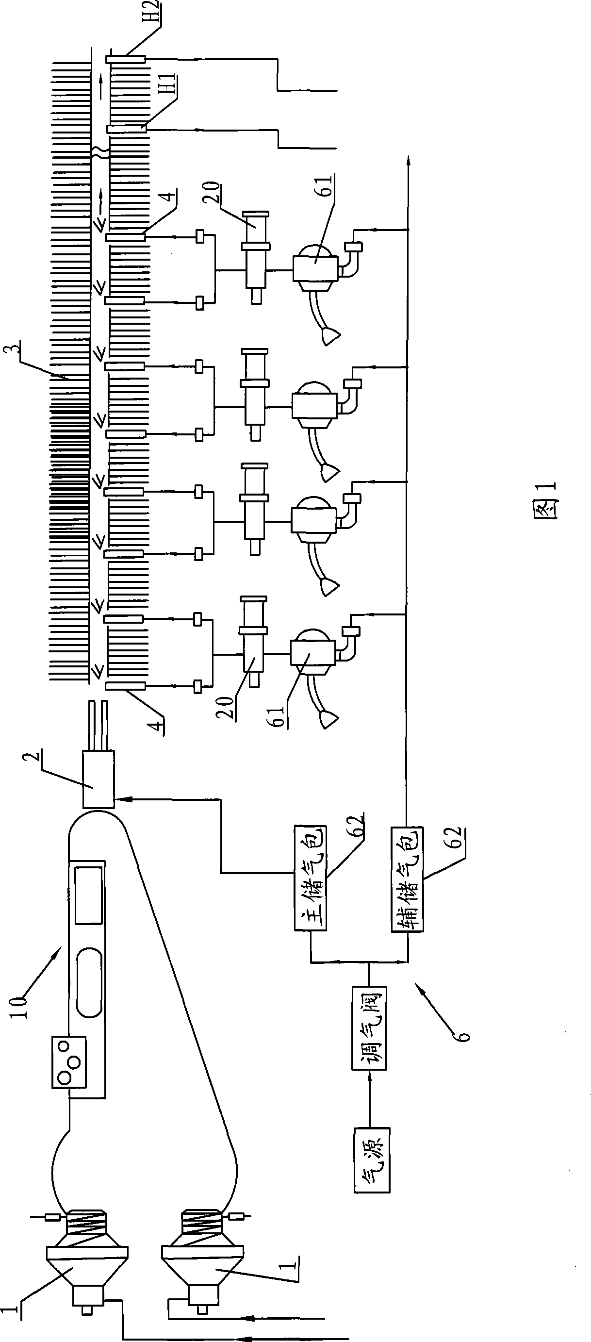
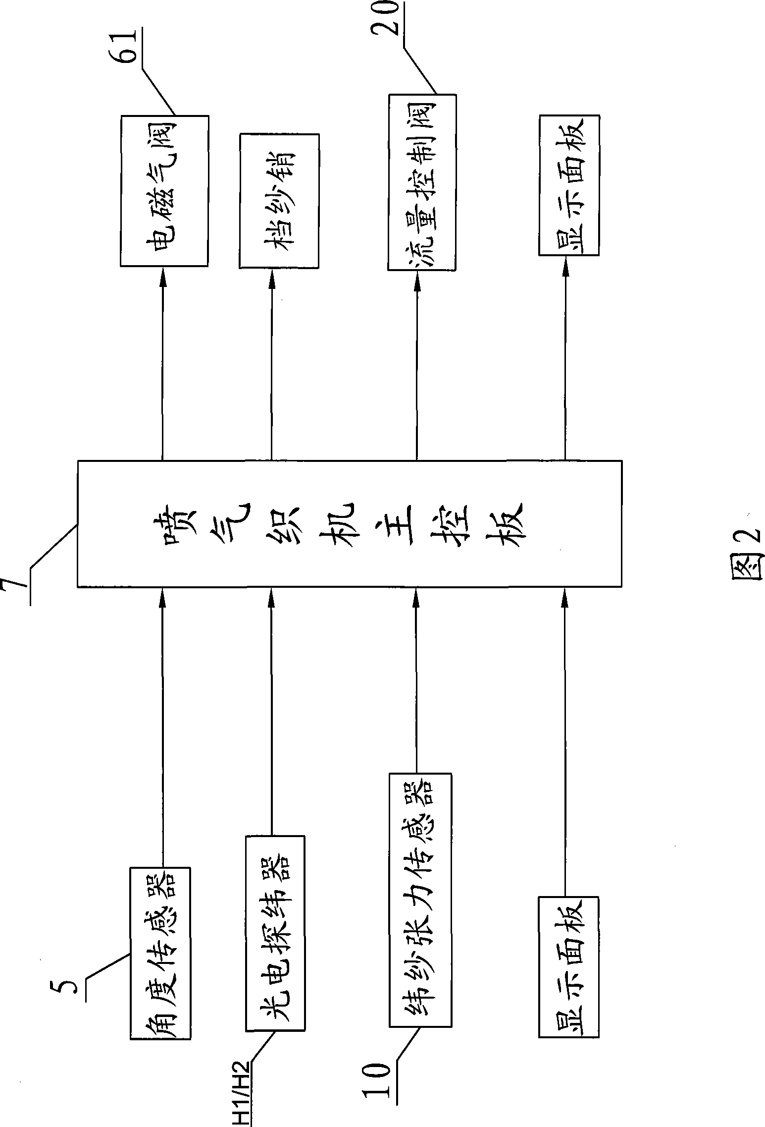
[0021] Air-jet loom weft insertion system as shown in Figure 1, it comprises the weft feeder 1 that is provided with retainer pin, main nozzle 2, special-shaped reed 3, a plurality of auxiliary nozzles 4 that are arranged along the reed width of special-shaped reed 3, The angle sensor 5 used to collect the angle signal of the main shaft of the air-jet loom, the photoelectric weft detector H1 and H2 arranged along the 3 reed widths of the special-shaped reed to collect the time when the weft yarn at the corresponding position reaches the weft catching side, are used for the described The main nozzle 2 and the auxiliary nozzle 4 provide the air supply mechanism 6 of the air source and the main control panel 7 of the air-jet loom (not shown in the figure), the main nozzle 2 is facing the shed direction, and the auxiliary nozzles 4 are distribut...


PUM


Abstract

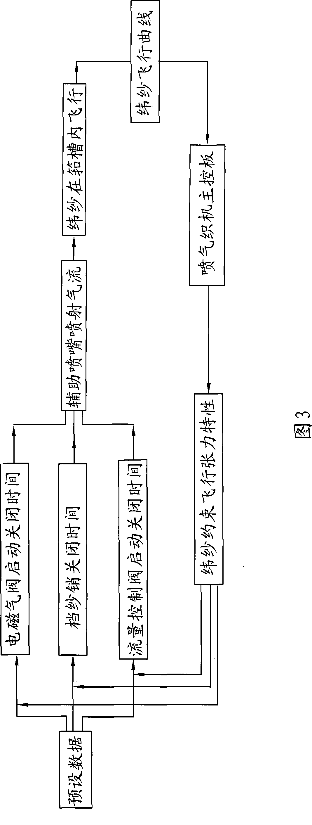
The invention relates to a control device for flying tension and fly time of weft of an air jet loom, which comprises a weft tension sensor that is arranged between a weft accumulator and a main jet, and a flow control valve that is arranged between a corresponding auxiliary jet and an electromagnetic air valve of an air flow supply mechanism. The invention also relates to a control method: (a) the start and the close times of the electromagnetic air valve, a weft-stop pin and the flow control valve on the main control panel of the air jet loom are preset; (b) a main axis angular senor collects the angle signal of a main axis, a photoelectric weft-finder collects the time information of the weft when the weft reaches the weft catching side, and the weft tension sensor collects the tension information of the weft while the weft flies; (c) the main control panel of the air jet loom processes the various information and adjusts the start and the close time parameters of each electromagnetic air valve, each weft-stop pin and each flow control valve, thus saving the air flow, namely, reducing the weft tension level of a restricted flying period by comparatively low air consumption, while prolonging the time of a restricted flying stage and reducing the weft broken rate.

Description

technical field [0001] The invention relates to a weft insertion system of an air-jet loom, in particular to a device for controlling weft yarn tension and weft time during weft insertion of an air-jet loom and a control method thereof. Background technique [0002] The air jet loom uses airflow to achieve weft insertion. The weft insertion system usually includes a weft feeder, a main nozzle, a special-shaped reed, multiple auxiliary nozzles arranged along the reed width, and an air supply mechanism that provides air sources for the main nozzle and each auxiliary nozzle. The air supply mechanism includes an air storage bag and an electromagnetic air valve. During weft insertion, each nozzle sprays according to the opening and closing time of the electromagnetic air valve preset by the main control board of the air-jet loom, and the multiple auxiliary nozzles arranged along the reed width spray The airflow forms the weft insertion airflow, each injection of each auxiliary no...

Claims


Application Information

Patent Timeline
IPC IPC(8): D03D49/26D03D49/50D03D47/34D03D47/30
Inventor 周平祝章琛
Owner WUJIANG WANGONG ELECTROMECHANICAL EQUIP
Learn More