Spreading roller for spreader

A technology of spreading rollers and stretching machines, which is applied in the fields of textile processing machine accessories, textiles and papermaking, and fabric surface trimming, and can solve the problems of difficulty in meeting the spreading needs of different fabrics, difficulty in adjusting the spreading width, and simple spreading mechanism and other problems, to achieve the effect of good spreading effect, various operation modes, and flexible sliding

Inactive Publication Date: 2009-06-03
SPEEDFLY ZHEJIANG AUTOMATION TECH
View PDF1 Cites 13 Cited by
  • Summary
  • Abstract
  • Description
  • Claims
  • Application Information

AI Technical Summary

Problems solved by technology

Although this solution effectively solves the problem of spreading when the stretching machine is running, the spreading mechanism is very simple, and the range of spreading is difficult to adjust, and it is difficult to meet the spreading needs of different fabrics
Moreover, the mechanism for adjusting the spread range is a link mechanism. During the operation of the whole machine, the link will loosen.

Method used


Image

  • Spreading roller for spreader
  • Spreading roller for spreader
  • Spreading roller for spreader

Examples


Embodiment Construction

[0018] In order to make the technical means, creative features, goals and effects achieved by the present invention easy to understand, the present invention will be further described below in conjunction with specific illustrations.

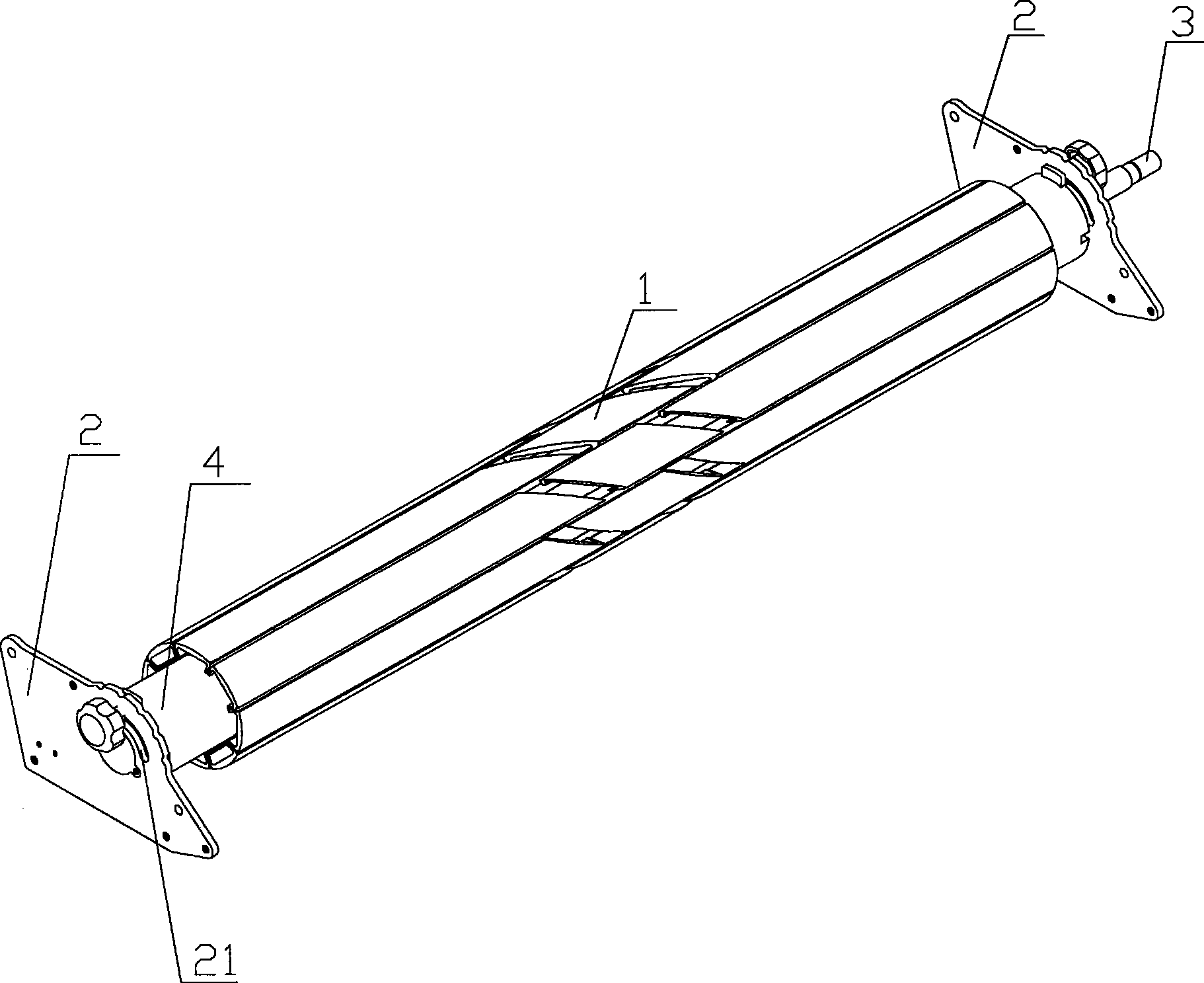
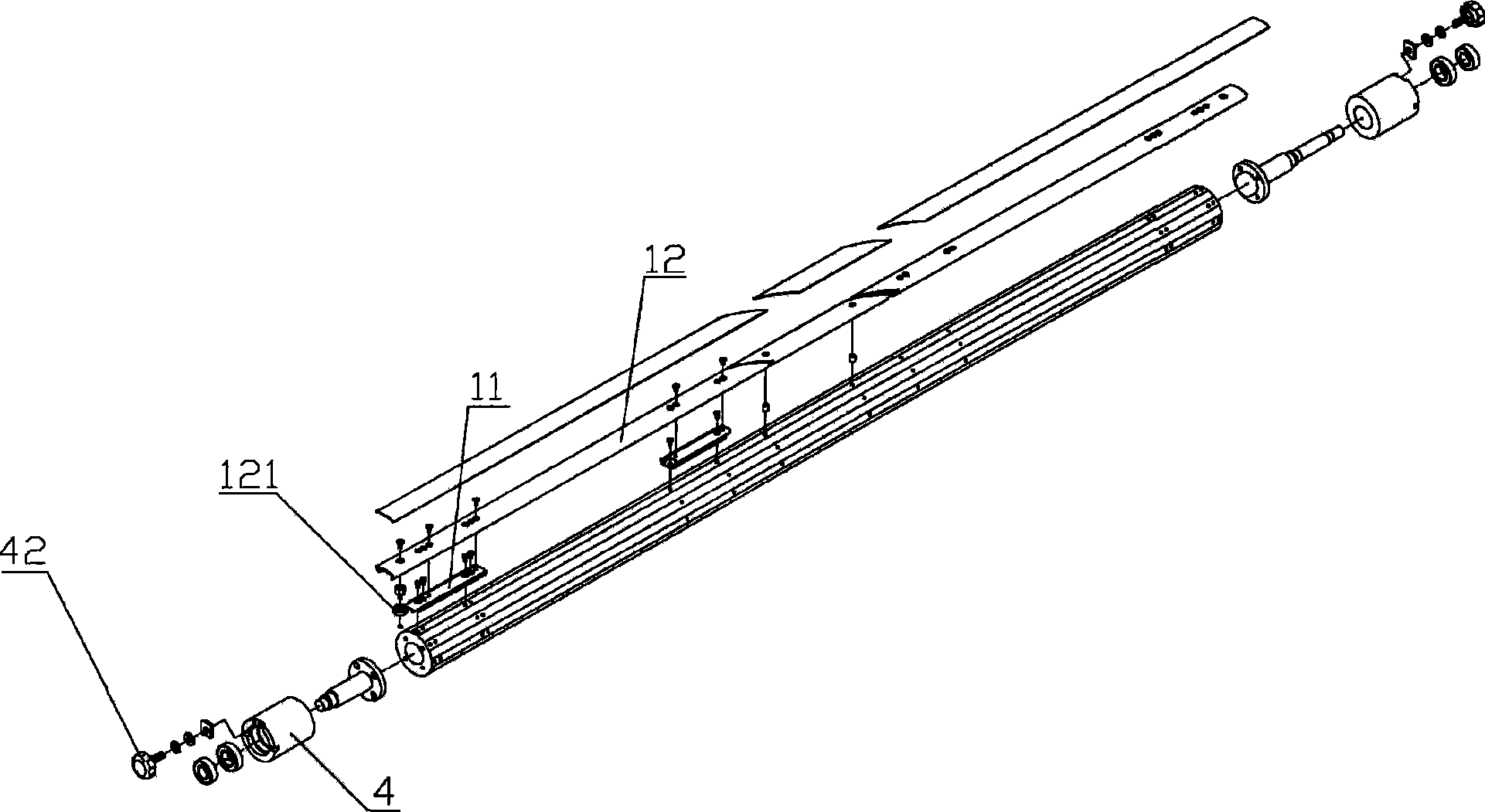
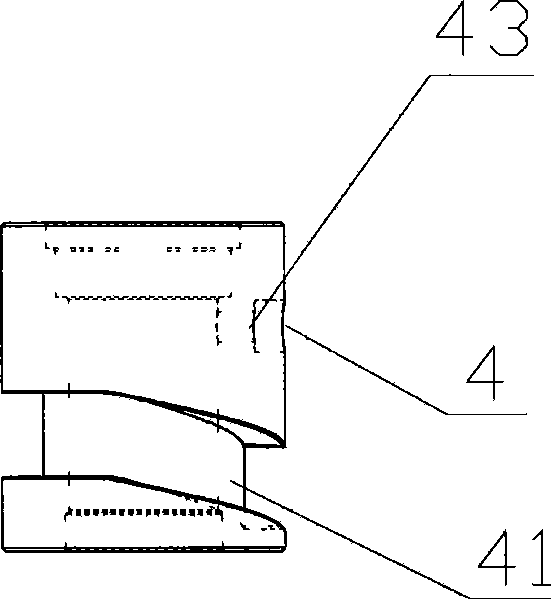
[0019] see figure 1 , figure 2 , image 3 , a spreader spreading roller, including a rotatable roller 1, the roller 1 is arranged on the roller frame 2, and one end of the roller 1 has a power input shaft 3, and the roller 1 is opposite to Roller frame 2 rotates, and described roller 1 is provided with slide rail 11, and described slide rail 11 is fixed on the roller 1 by bolt, and described slide rail 11 is symmetrically arranged on roller 1 left and right, on slide rail 11 There are blades 12 for spreading. The ends of the blades 12 have sheave contacts 121. The outer surface of the blades 12 is provided with blade skins 13. The blade skins 13 are diving cloths with relatively large frictional force relative to the cloth surface. The diving...


PUM


Abstract

The invention relates to a spreading roller for a spreader, comprising the rotary roller. The roller is arranged on a roller frame; one end of the roller is provided with a power input shaft; a plurality of blades which can slide left and right, are symmetric left and right and are used for spreading are arranged on the roller; and grooved pulleys for driving the blades to slide left and right are arranged at the two ends of the roller. The spreading roller is characterized in that a slide rail is arranged on the roller; the blades are connected with the slide rail; the end part of the blade is provided with a grooved pulley contact; the outer surface of the blade is provided with blade skin; the grooved pulleys are fixedly connected on a roller frame at the two sides; the grooved pulley is provided with an annular skewed slot; the contact is embedded in the skewed slot in a sliding way; and the grooved pulleys are fixed on the roller frame by a locking bolt. During the spreading, the roller rotates, and the grooved pulleys do not move; the grooved pulleys drive the blades to slide left and right. During the adjusting of the spreading range, the locking positions of the grooved pulleys are adjusted for changing the spreading range of the blades. When the spreading function is not required, the locking bolt is cancelled, and the grooved pulleys are fixed on a rotary shaft by a fixing pin, so that the blades cannot slide left and right.

Description

technical field [0001] The invention relates to the technical field of clothing equipment machinery, in particular to a spreading roller of a spreading machine. Background technique [0002] The stretching machine can lay the roll of cloth on the machine table. The way of laying is through the movable casing that can slide on the upper end of the machine table, and use its reciprocating movement on the machine table to continuously reciprocate and turn the cloth and gradually Stack high, and then use other machines to cut multi-layered fabrics into clothes of the same style. [0003] Generally, the traditional stretching machine does not have a special design structure. Because some fabrics are soft materials, especially knitted fabrics, which are stretchable, the fabric will be slightly stretched in the direction of travel when pulling, but slightly stretched on both sides. Shrinkage, after being pulled to a certain length, the elastic recovery force of the fabric often ca...

Claims


Application Information

Patent Timeline
Patent Type & Authority Applications(China)
IPC IPC(8): D06C3/00D06B23/00
Inventor 邓江荣
Owner SPEEDFLY ZHEJIANG AUTOMATION TECH
Why Eureka
Try Eureka