Two-stage friction type dual-mass flywheel

A dual-mass flywheel, friction-type technology, applied in vibration suppression adjustment, spring/shock absorber, mechanical equipment, etc., can solve the problems of small torsion angle and ineffective reduction of torsional stiffness, avoiding resonance and excellent vibration reduction. Effects, effects with a simple structure

Inactive Publication Date: 2009-06-03
CHONGQING GUANGDA IND +1
View PDF0 Cites 20 Cited by
  • Summary
  • Abstract
  • Description
  • Claims
  • Application Information

AI Technical Summary

Problems solved by technology

The small torsional angle and constant torsional stiffness of the dual-mass flywheel

Method used


Image

  • Two-stage friction type dual-mass flywheel
  • Two-stage friction type dual-mass flywheel
  • Two-stage friction type dual-mass flywheel

Examples


Embodiment 1

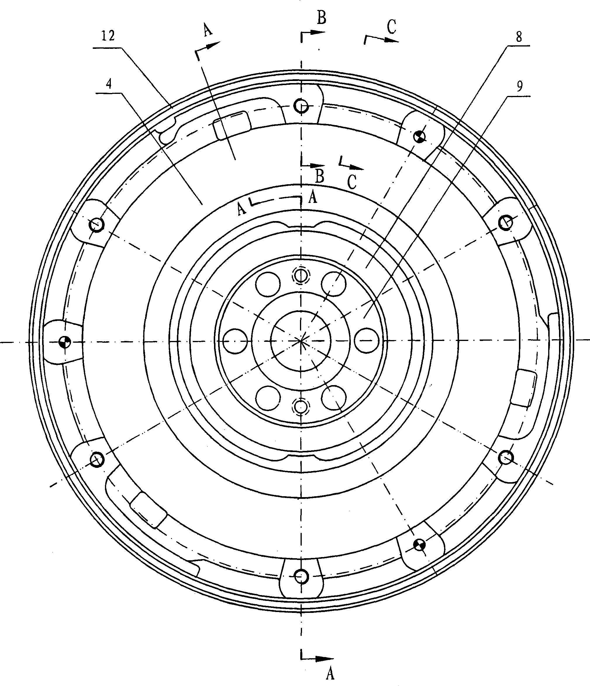
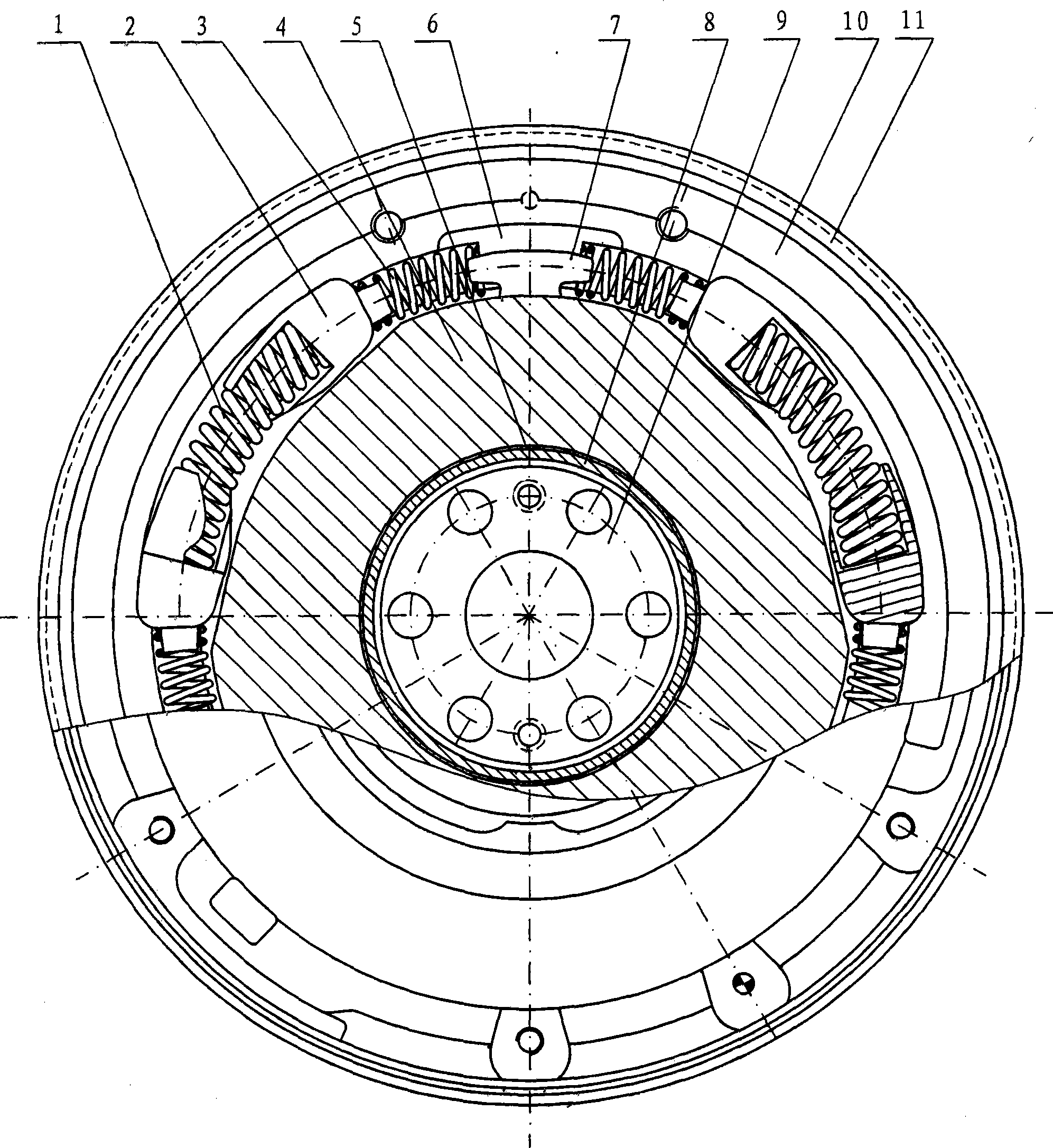
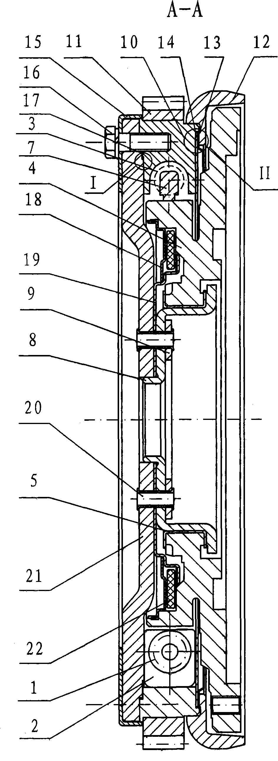
[0135] A 2.0L car engine uses a dual-stage friction dual-mass flywheel. The dual-mass flywheel includes a first spring 1, a spring seat 2, a second spring 3, a secondary flywheel 4, a washer 5, a pressure block 6, a shift block 7, and an end Cover 8, cushion block 9, primary flywheel 10, starting ring gear 11, ferrule 12, right ring 13, left ring 14, pressure plate 15, gasket 17, backing ring 18, connection plate 19, pin sleeve 20, cover plate 21 and ring block 22. Three central angles α are evenly distributed on the inner wall of the axial circular through hole of the primary flywheel 10 10 Both are 56°, inner radius R 10 The first annular bosses are all 100mm, and each of the three first annular bosses has a central angle α in the middle of the surface 11 is 28°, inner and outer radius R 11 , R 12 100mm and 116mm annular grooves respectively, the radial sections of the annular through grooves whose inner openings in the three first annular bosses are all towards the cent...

Embodiment 2

[0144] 2.3L—2.4L car engine with two-stage friction dual-mass flywheel, the dual-mass flywheel includes a first spring 1, a spring seat 2, a second spring 3, a secondary flywheel 4, a washer 5, a pressing block 6, and a shifting block 7. End cover 8, pad 9, primary flywheel 10, starting ring gear 11, ferrule 12, right ring 13, left ring 14, pressure plate 15, gasket 17, backing ring 18, connecting plate 19, pin sleeve 20, Cover plate 21 and ring block 22 . Three central angles α are evenly distributed on the inner wall of the axial circular through hole of the primary flywheel 10 10 Both are 56°, inner radius R 10 The first annular bosses are all 100mm, and each of the three first annular bosses has a central angle α in the middle of the surface 11 is 28°, inner and outer radius R 11 , R 12 100mm and 116mm annular grooves respectively, the radial sections of the annular through grooves whose inner openings in the three first annular bosses are all towards the center of the...


PUM

PropertyMeasurementUnit
Radiusaaaaaaaaaa
Thicknessaaaaaaaaaa
Shear modulus of elasticityaaaaaaaaaa

Abstract

A two-stage friction type dual-mass flywheel between the engine and the clutch gearbox of a car comprises a spring, a spring seat, a secondary flywheel, a washer, an end cover, a cushion block, a primary flywheel, a startup ring gear, a right ring, a left ring, a backing ring, a connecting plate, a pin bush and a circular block. The invention provides a dual-mass flywheel which can achieve two-stage variable stiffness transmission, and aims to overcome defaults that the torsion angle of a single-stage circumferential short spring dual-mass flywheel is small and the variable stiffness transmission can not be achieved. The invention ensures that the torsion angle is increased; the two-stage variable stiffness transmission is realized; the first nature frequency of a transmission system is enabled to be greatly lower than exciting frequency, and the second nature frequency is higher than the exciting frequency of the maximum turning speed of an engine, thereby avoiding resonance; the friction effects among the spring seat, the primary flywheel and the secondary flywheel ensure that various torque characteristics can be produced when the torsion angle is incresed or decresed; the normal pressure on the spring seat is reduced; and the service life of the spring seat is prolonged.

Description

technical field [0001] The invention relates to a dual-mass flywheel of a power assembly of an automobile transmission system, in particular to a dual-mass flywheel between a car engine and a clutch gearbox. Background technique [0002] GAT Drive Technology, a joint venture between ZF and GIF, Germany, introduced a dual-mass flywheel in the 1980s. The dual mass flywheel includes a primary flywheel subassembly, a secondary flywheel subassembly and a torsional vibration damper. Among them, the primary flywheel subassembly includes starting ring gear, primary flywheel, right ring, left ring, and the secondary flywheel subassembly includes secondary flywheel, backing ring, connecting plate, pad, pin sleeve, washer, ring block, twist The vibration damper consists of 6 springs, each spring is fixed in the spring chamber of the primary flywheel by two spring seats. The primary flywheel subassembly is connected to the secondary flywheel subassembly by bolts. The small torsional ...

Claims


Application Information

Patent Timeline
IPC IPC(8): F16F15/134
Inventor 刘世勇宋立权罗书明赵孝峰田宏艳
Owner CHONGQING GUANGDA IND
Why Eureka
Try Eureka