

Workpiece supporting device
A technology for supporting devices and workpieces, which is applied in the direction of furnace components, electrical components, conveyor objects, etc., and can solve the problems of the balance damage of workpiece W quality and gas flow, difficult correspondence, unstable support posture, etc.
- Summary
- Abstract
- Description
- Claims
- Application Information
AI Technical Summary
Problems solved by technology
Method used
Image

Examples
Embodiment Construction
[0040] Hereinafter, one embodiment will be described in detail with reference to the drawings for the workpiece supporting device of the present invention.
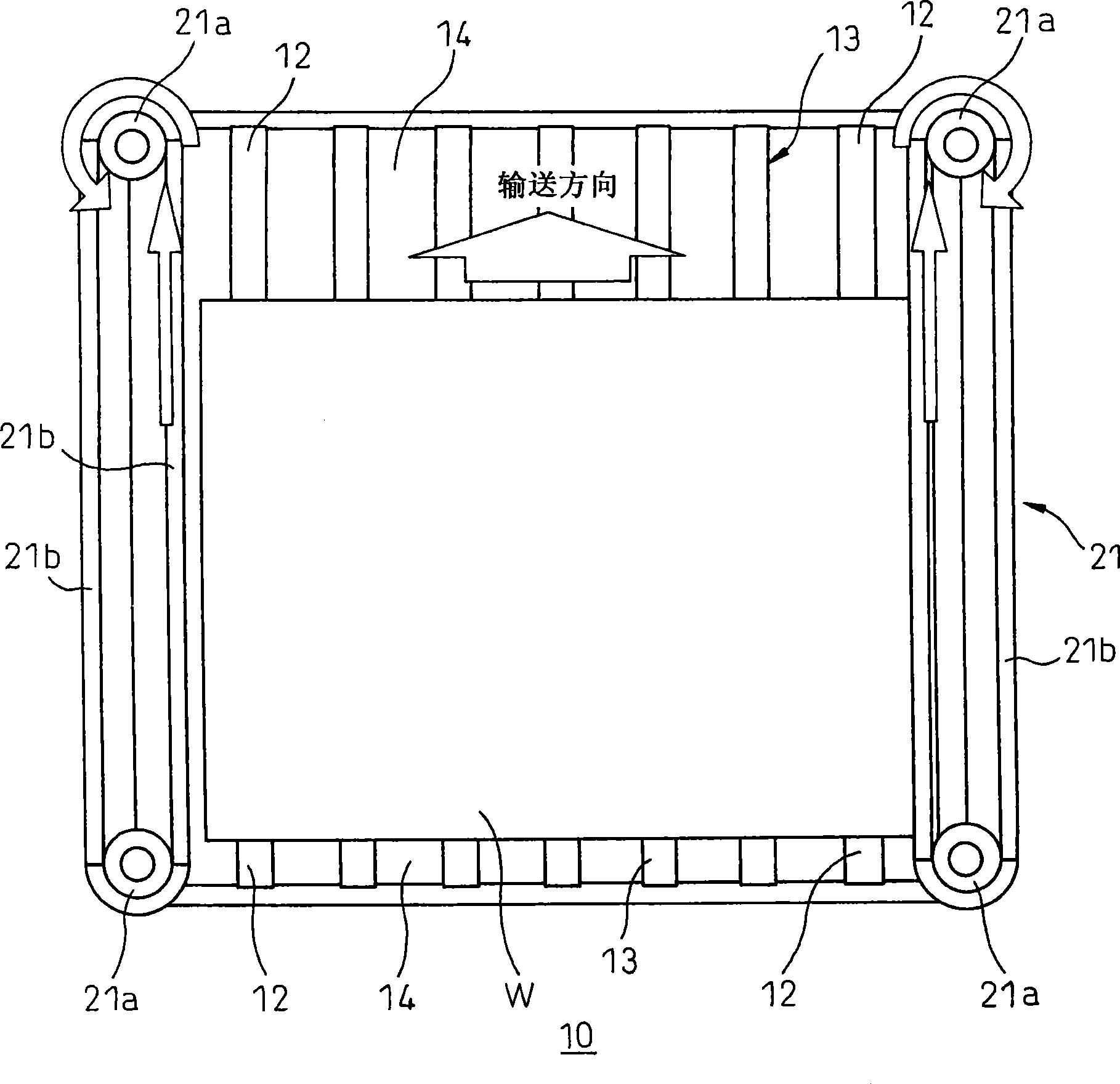
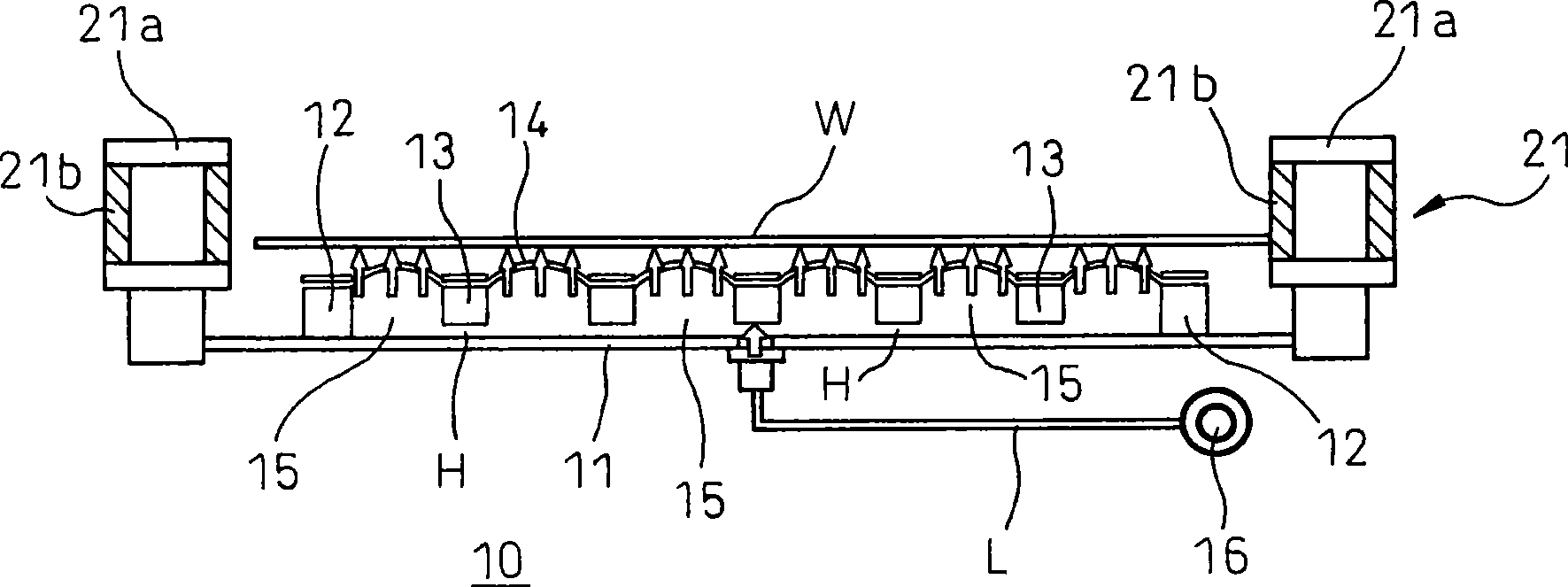
[0041] figure 1 , figure 2 The middle part schematically shows the main part of the support device 10 for the thinned film-shaped workpiece W as the workpiece.
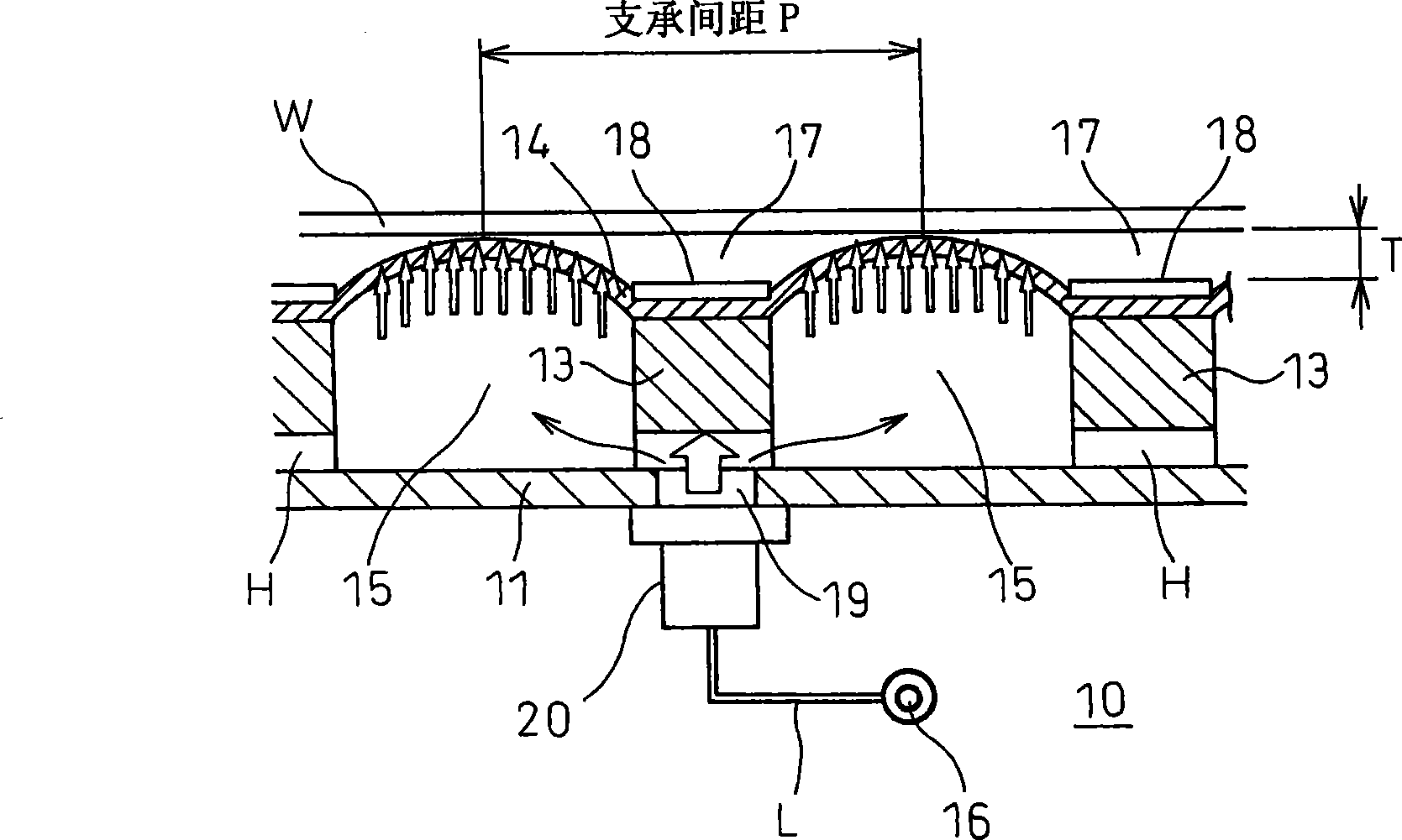
[0042] The support device 10 includes an airtight frame member 12 disposed on the base 11, at least one mounting member 13 disposed on the base 11 inside the frame member 12, and a porous air-permeable frame supported by the frame members 12 and the mounting member 13. The sheet 14 and the pressurized gas supply source 16 for supplying pressurized gas to the sealed space 15 partitioned by the air permeable porous sheet 14 , the frame member 12 and the base 11 .
[0043] The base 11 is a flat member made of a square member with a bottom area at least large enough to place the entire workpiece W to be supported and transported, and a frame member 12 protrudes f...
PUM
 Abstract
Description
Claims
Application Information