
Antenna device and electronic apparatus

An antenna device and antenna module technology, applied in resonant antennas, independent antenna unit combinations, slender active unit end feeds, etc., can solve problems such as installation flexibility limitations

Inactive Publication Date: 2009-06-03
KK TOSHIBA
View PDF1 Cites 4 Cited by
  • Summary
  • Abstract
  • Description
  • Claims
  • Application Information

AI Technical Summary

Problems solved by technology

In addition, since the antenna pattern is formed on the surface (plane) of the substrate, an installation space stretching in the horizontal direction is required, and installation flexibility is limited

Method used


Image

  • Antenna device and electronic apparatus
  • Antenna device and electronic apparatus
  • Antenna device and electronic apparatus

Examples


Embodiment Construction

[0018] Various embodiments according to the present invention will be described below with reference to the drawings.

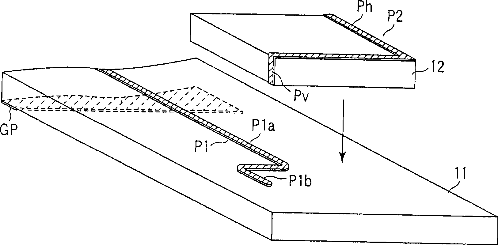
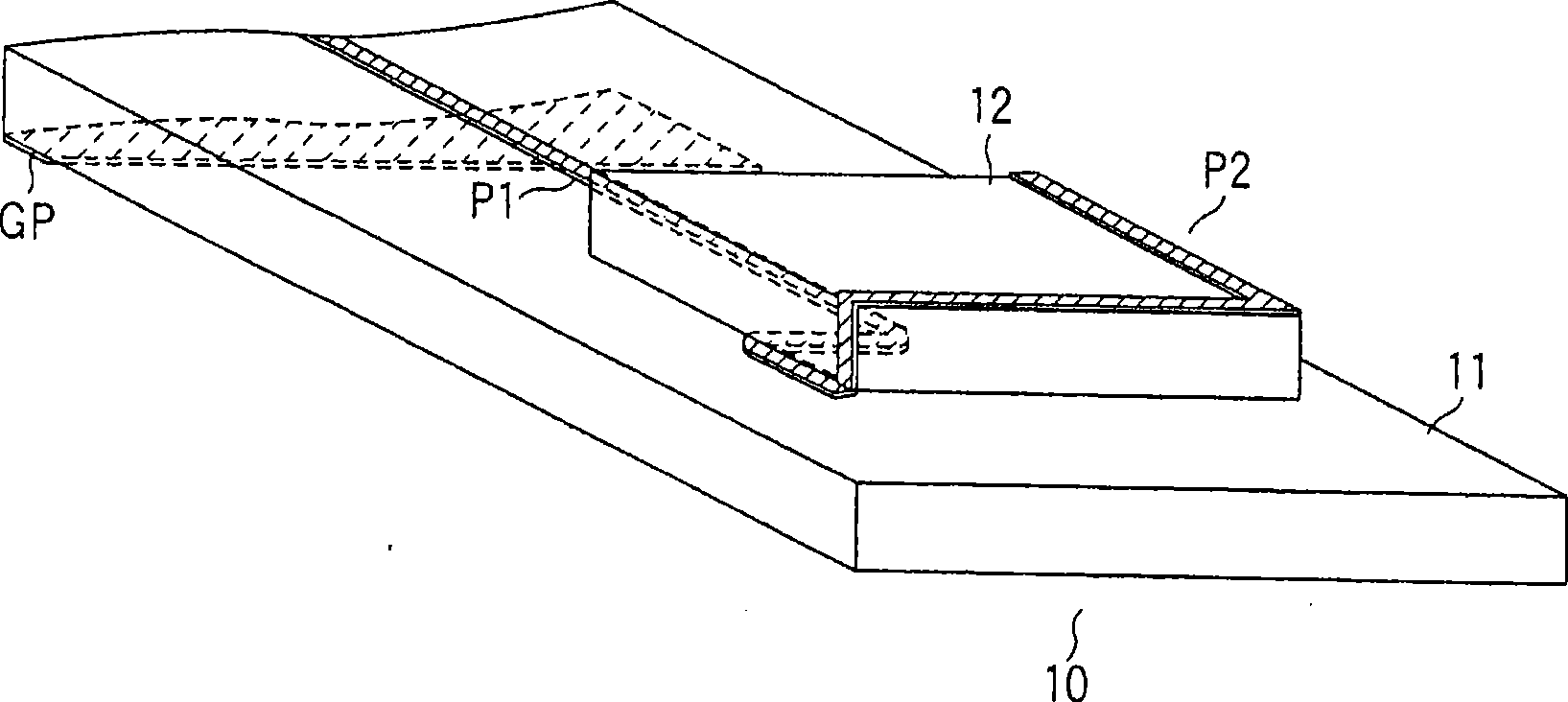
[0019] Figure 1A with 1B An example of the antenna device according to the first embodiment of the present invention is shown. Figure 1A Shows the state before the elements of the antenna unit are combined. Figure 1B Shows the state after the elements of the antenna unit are assembled.

[0020] Such as Figure 1A with 1B As shown, the antenna device according to the first embodiment includes a base 11 having a feeding pattern P1, and a stackable block (substrate) 12 stacked on the base 11 and fixed to the surface of the substrate, the stackable block 12 having One end is conductively connected to the feed pattern P1 and the other end may extend in a direction in which another stackable block is stacked on the stackable block 12 .

[0021] The base 11 and the stackable block 12 are made of printed circuit boards, and the feed pattern P1 and element patte...


PUM


Abstract

According to one embodiment, there is provided an antenna device including a base substrate having a power-feeding pattern, and a stackable block stacked on the base substrate and fixed to the surface of the base substrate, the stackable block having an element pattern with one end connected to the power-feeding pattern and the other end extendible in a direction of stacking another stackable block on the stackable block.

Description

technical field [0001] One embodiment of the present invention relates to an antenna arrangement suitable for a transportable small electronic device equipped with a radio unit. Background technique [0002] Internal antennas using printed circuit boards are often used in small transportable electronic devices equipped with radio units. An internal antenna using a printed circuit board is constructed by forming, on the printed circuit board, an element pattern having a printed wiring board structure, which functions as an antenna radiator. Similar to circuit wiring patterns in printed wiring boards, component patterns are made of conductive foil. In a conventional antenna device using such a printed circuit board, element patterns are formed on a single board or a multilayer board. Such antenna devices are disclosed, for example, in Japanese Patent Application KOKAI Publication Nos. 2002-100915, 2005-005987 and 2004-186730. [0003] In the above conventional antenna devic...

Claims


Application Information

Patent Timeline
Patent Type & Authority Applications(China)
IPC IPC(8): H01Q1/38H01Q9/30H01Q21/30
CPCH01Q9/42H01Q1/38H01Q21/30
Inventor 广田敏之元永宽则
Owner KK TOSHIBA
Learn More