Television network image monitoring system and monitoring method thereof

A technology of TV network and monitoring system, applied in the direction of TV, image communication, electrical components, etc., can solve the problems of slow recovery progress, waste of human and material resources, and timely recovery of unfavorable TV program image quality, so as to facilitate monitoring and maintenance, reduce The effect of operating costs

Active Publication Date: 2012-06-13
GCI SCI & TECH
View PDF0 Cites 0 Cited by
  • Summary
  • Abstract
  • Description
  • Claims
  • Application Information

AI Technical Summary

Problems solved by technology

Among them, the HFC (Hybrid Fiber Coaxial Cable, fiber-coaxial cable hybrid network) network has become the most mature and market-oriented TV program transmission network in the existing technology due to its advantages of large transmission data capacity and low network architecture cost. In the various existing TV network structures, TV program signals are transmitted unidirectionally to the TV set at the user end. Due to the unidirectional nature of the TV network, it is impossible to know the broadcasting of TV programs at each node in the TV network through the remote end. Therefore, when there is a problem with the image quality of a TV program, TV network maintenance personnel need to go to the user's home to check the fault step by step, which consumes a lot of manpower and material resources, and the recovery progress is slow, which is not conducive to the image quality of the TV program. timely recovery

Method used


Image

  • Television network image monitoring system and monitoring method thereof
  • Television network image monitoring system and monitoring method thereof
  • Television network image monitoring system and monitoring method thereof

Examples


Embodiment 1

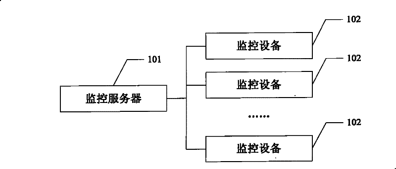
[0022] see figure 1 As shown, it is a schematic structural diagram of Embodiment 1 of the television network monitoring system of the present invention.

[0023] Such as figure 1 As shown, the television network monitoring system in this embodiment includes a monitoring server 101 and at least one monitoring device 102 connected to the monitoring server 101, wherein the monitoring server 101 and the monitoring device 102 can be connected by optical fiber, coaxial cable, etc. , the monitoring server 101 can be set at the monitoring personnel or maintenance personnel's terminal of the TV network to realize the monitoring of the entire TV network, and the monitoring device 102 can be set at a node of the TV network, such as a floor user's or a floor user's The TV program conversion point can also be set at the terminal of each TV program signal, that is, a monitoring device 102 can be set at each TV program user terminal. For the consideration of construction cost and maintenanc...

Embodiment 2

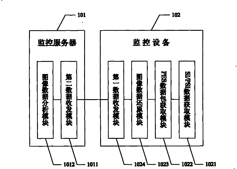
[0035] see figure 2 As shown, it is a schematic structural diagram of Embodiment 2 of the television network monitoring system of the present invention. In this embodiment, the main difference from the above Embodiment 1 is that the monitoring server 101 and the monitoring device 102 are implemented in this embodiment. To further limit, in the following description, for simplicity, only one of the monitoring devices is used for description.

[0036] Such as figure 2 As shown, in this example the

[0037] The monitoring equipment 102 of the TV network monitoring system specifically includes:

[0038] SI / PSI data acquisition module 1021, configured to search for SI / PSI data according to the monitoring instruction, the monitoring instruction includes program identification information;

[0039] The PES data packet obtaining module 1022 connected with the SI / PSI data obtaining module 1021 is used to obtain the PID of the PES data packet of the TV program corresponding to the ...

Embodiment 3

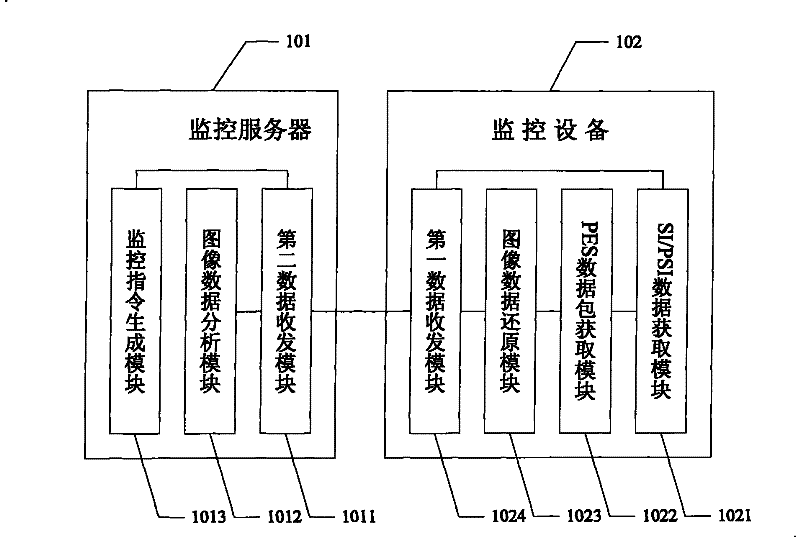
[0050] see image 3 As shown, it is a schematic structural diagram of Embodiment 3 of the television network monitoring system of the present invention. In this embodiment, the difference from the above Embodiment 2 mainly lies in that the monitoring server 101 in this embodiment also includes:

[0051] A monitoring instruction generating module 1013 connected to the second data transceiving module 1011, configured to generate the monitoring instruction;

[0052] The second data transceiving module 1011 is further configured to send the monitoring instruction to the monitoring device 102;

[0053] The first data transceiver module 1024 of the monitoring device 102 is also connected to the SI / PSI data acquisition module 1021, and the SI / PSI data acquisition module 1021 acquires SI according to the monitoring instruction of the monitoring server 101 received by the first data transceiver module 1024. / PSI data.

[0054] Wherein, when the monitoring server 101 sends the monitor...


PUM


Abstract

The invention provides a television network image monitoring system and a monitoring method thereof. The monitoring method comprises the following steps: monitoring equipment receives a monitoring instruction and searches for SI / PSI data of a corresponding television program according to the monitoring instruction, obtains a PID of a corresponding PES data package from the SI / PSI data, obtains the relevant PES data package according to the PID of the PES data package, restores television image data of the television program according to the PES data package and sends the image data to a monitoring server, the monitoring server can analyze whether a television image of the television programs corresponding to the image data is abnormal based on the restored image data, thus effectively andimmediately monitoring the image of the television program, if the television image is abnormal, the monitoring server can immediately locate the abnormal television image. The television network image monitoring system and the monitoring method facilitate maintainers to monitor and maintain a whole television network and reduce the operation cost.

Description

technical field [0001] The invention relates to the technical field of digital television networks, in particular to a television network image monitoring system and monitoring method. Background technique [0002] With the increasing popularity and wide application of cable TV, especially digital TV, people's lives have undergone earth-shaking changes, especially after the adoption of digital TV, the TV programs people see are clearer and the number of programs is larger under the digital platform. More information can be obtained, and the content is richer, which satisfies people's growing spiritual and cultural needs to a certain extent. Among them, the HFC (Hybrid Fiber Coaxial Cable, fiber-coaxial cable hybrid network) network has become the most mature and market-oriented TV program transmission network in the existing technology due to its advantages of large transmission data capacity and low network architecture cost. In the various existing TV network structures, ...

Claims


Application Information

Patent Timeline
Patent Type & Authority Patents(China)
IPC IPC(8): H04N17/00
Inventor 金志琛
Owner GCI SCI & TECH
Why Eureka
Try Eureka