

Uplink control signal path resource mapping method in large bandwidth system and device thereof
A technology for controlling channel resources and control channels, which is applied in the field of mobile wireless communications to ensure compatibility and maintain flexibility
- Summary
- Abstract
- Description
- Claims
- Application Information
AI Technical Summary
Problems solved by technology
Method used
Image

Examples
Embodiment 1
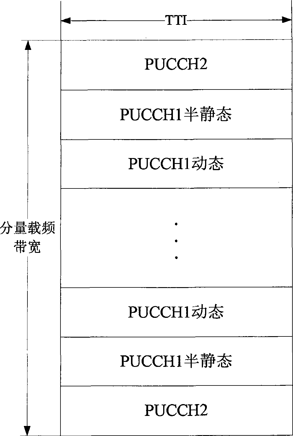
[0073] According to the method, the signaling type carried by the PUCCH is mapped in blocks (that is, in regions), and the PUCCH resources of all component carrier frequencies are continuously mapped in each block according to the component carrier frequencies.
[0074] Specifically,
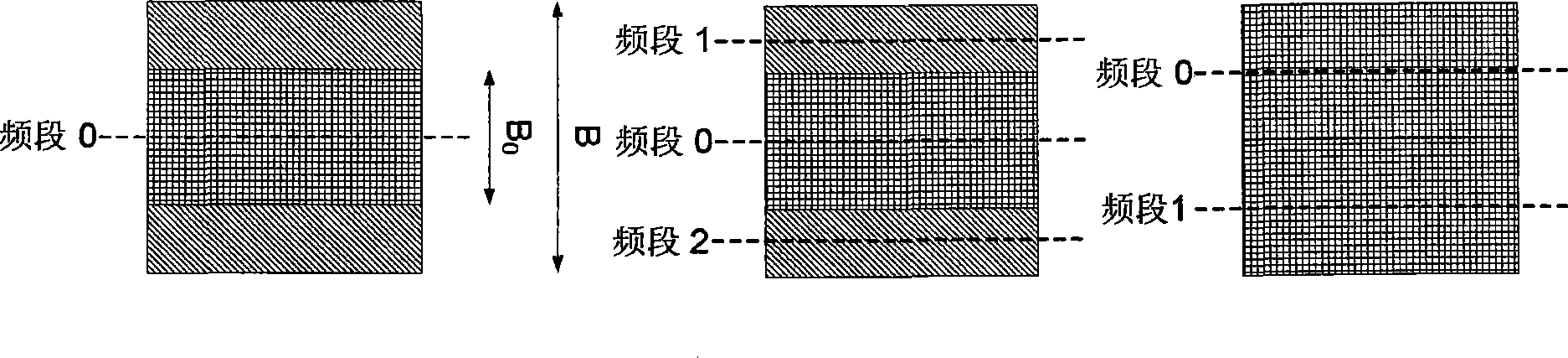
[0075] Assume that a certain uplink component carrier frequency corresponds to two downlink component carrier frequencies (component carrier frequency 1 and component carrier frequency 2 respectively), and resources are divided into blocks according to PUCCH types in the PUCCH resource region.
[0076] Such as Figure 4 As shown, in each block of a PUCCH type, the PUCCH resources of this type of all component carriers are sequentially mapped and arranged according to the component carrier frequencies. The PUCCH resource of component carrier frequency 1 is first mapped sequentially, and then the PUCCH resource of component carrier frequency 2 is sequentially mapped.
[0077] Such as Figure 8 ...
Embodiment 2
[0079] In this method, block mapping is performed according to the PUCCH type. In each block, the PUCCH resources of all component carrier frequencies are interleaved and mapped in blocks according to the component carrier frequencies, or the PUCCH resources of each component carrier frequency in a block can be dynamically allocated through high-layer signaling.
[0080] Assume that at this time, a certain uplink component carrier frequency corresponds to two downlink component carrier frequencies (component carrier frequency 1 and component carrier frequency 2 respectively), and resources are divided into blocks according to PUCCH types in the PUCCH resource region.
[0081] Such as Figure 5 As shown, in each PUCCH-type block, each component carrier maps and arranges the PUCCH indexes of all component carriers in blocks and interleaves (first maps the first part of PUCCH resources of component carrier 1 in order of interleaving size, and then maps The first part of PUCCH re...
Embodiment 3
[0084] The method maps in blocks according to the PUCCH type, and continuously maps the PUCCH resources of all component carrier frequencies in each block according to the component carrier frequencies.
[0085] Specifically,
[0086] by Image 6 For example, at this time, an uplink component carrier corresponds to three downlink component carriers (component carrier 1, component carrier 2, and component carrier 3), and resources are divided into blocks according to the PUCCH type in the PUCCH resource area . In each PUCCH type block, map and arrange all the PUCCH resources of this type of component carrier frequency in sequence according to the component carrier frequency (first map the PUCCH resource of component carrier frequency 1, then map the PUCCH resource of component carrier frequency 2, and finally map PUCCH resource of component carrier frequency 3). In each PUCCH type block, all resource indexes are arranged in descending order.
PUM
 Abstract
Description
Claims
Application Information