Apparatus for optical parametric chirped pulse amplification (opcpa) using inverse chirping and idler

A technology for optical parametric amplification and idler signals, applied in optics, lasers, nonlinear optics, etc., can solve problems such as complex structures, increased construction costs, and difficult adjustment of optical systems

Inactive Publication Date: 2009-06-03
KOREA ADVANCED INST OF SCI & TECH
View PDF0 Cites 11 Cited by
  • Summary
  • Abstract
  • Description
  • Claims
  • Application Information

AI Technical Summary

Problems solved by technology

[0047] That is to say, the problem of the conventional OPCPA device is that, because it will antiparallel diffraction grating structure (refractive type, reflective type, and Offner triple type) (cf. figure 2 to 4) applied to the optical pulse stretcher, and parallel diffraction grating structure (refer to Figure 7 ) is applied to the optical pulse compressor, and the structure of the optical pulse structure is too complicated
Therefore, the structure of the conventional OPCPA device is complicated, the adjustment of the optical system becomes difficult, and the construction cost increases

Method used


Image

  • Apparatus for optical parametric chirped pulse amplification (opcpa) using inverse chirping and idler
  • Apparatus for optical parametric chirped pulse amplification (opcpa) using inverse chirping and idler
  • Apparatus for optical parametric chirped pulse amplification (opcpa) using inverse chirping and idler

Examples


Embodiment Construction

[0087] Hereinafter, embodiments of the present invention will be described in detail with reference to the accompanying drawings.

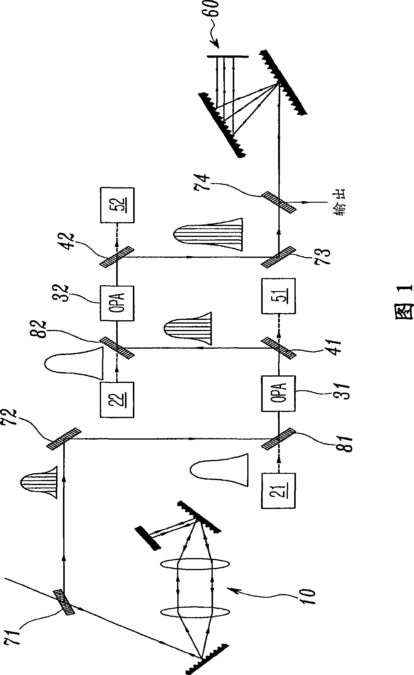
[0088] FIG. 5 is a block diagram of an optical parametric chirped pulse amplification (OPCPA) device according to the present invention, and FIG. 6 is a detailed schematic diagram showing the structure of the OPCPA device of FIG. 5 .

[0089] Referring to Fig. 5 and Fig. 6, the OPCPA device according to the present invention comprises: optical pulse stretcher 100, pump laser 210 and 220, optical parametric amplification (OPA) unit 310 and 320, optical signal separation unit 410 and 420, beam collection Units (beam dumps) 510 and 520 , and an optical pulse compressor 600 .

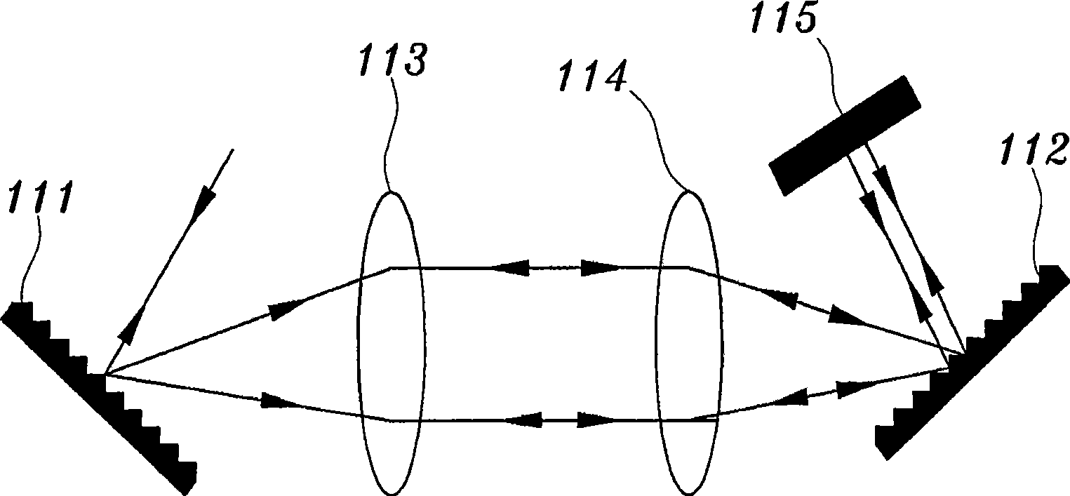
[0090] The optical pulse stretcher 100 is a device for temporarily stretching the laser light by changing the optical path for each frequency of the laser light, employing a short-wavelength-first type chirp (refer to Figure 9 ). That is, the optical pulse stretcher 100 temp...


PUM


Abstract

An OPCPA apparatus of the present invention includes an optical pulse stretcher (100) for temporally stretching laser light, and applying short-wavelength preceding-type chirping. Pump lasers (210, 220) emit pump laser light. A first OPA unit (310) receives the pump laser light, and a signal having passed through the optical pulse stretcher, amplifies the signal, and generates a first idler. A first optical signal separation unit (410) separates output light of the first OPA unit into the first idler and remaining light (pump and signal). A second OPA unit (320) receives the first idler and another pump laser light, amplifies the first idler, and generates a second idler. A second optical signal separation unit (420) separates output light of the second optical parametric amplification unit into an amplified first idler and remaining light (pump and second idler). An optical pulse compressor (600) temporally compresses the amplified first idler.

Description

technical field [0001] The present invention generally relates to a kind of Optical Parametric Chirped Pulse Amplification (OPCPA, OpticalParametric Chirped Pulse Amplification) device, more specifically, relates to a kind of OPCPA device using negative chirp and idler signal (idler), the device amplifies mode-locked ( mode-locked) ultrashort-wave laser source, which exists in the band range from tens of femtoseconds (fs; 10 -15 seconds, femtosecond) to several picoseconds (ps: 10 -12 seconds, picosecond) in the band. Background technique [0002] Optical parametric chirped pulse amplification (OPCPA) is a new optical amplification technology that combines the traditional chirped pulse amplification (CPA) technology with the concept of optical parametric amplification (OPA), and is a laser amplification technology that has been actively researched recently. [0003] In the traditional OPCPA device, the antiparallel diffraction grating structure adopting the long-wavelength...

Claims


Application Information

Patent Timeline
Patent Type & Authority Applications(China)
IPC IPC(8): H01S3/10
CPCG02F2001/392G02F1/39G02F1/392H01S3/10
Inventor 孔弘珍李东原崔振白枓贤尹镇雨金泰亨
Owner KOREA ADVANCED INST OF SCI & TECH
Why Eureka
Try Eureka