Practical approach for one mJ femtosecond fiber laser

a fiber laser and fiber laser technology, applied in the direction of lasers using scattering effects, laser details, electrical equipment, etc., can solve the problems of depleting signal power, limited fiber laser systems, and ordinary skill in the art, and achieve the effect of extending the spectrum

Active Publication Date: 2007-08-02
POLARONYX
View PDF1 Cites 17 Cited by
  • Summary
  • Abstract
  • Description
  • Claims
  • Application Information

AI Technical Summary

Benefits of technology

[0005]It is therefore an aspect of the present invention to provide a laser system wherein the laser transmission is provided to take advantage of the SPM to broaden the spectrum in

Problems solved by technology

Even though current technologies of fiber laser have made significant progress toward achieving a compact and reliable fiber laser system providing high quality output laser with ever increasing output energy, however those of ordinary skill in the art are still confronted with technical limitations and difficulties.
Specifically, in a fiber laser system implemented with the Chirped Pulse Amplification (CPA) for short pulse high power laser amplifier, the fiber laser systems are still limited by the technical difficulties that 1 mJ high energy femtosecond fiber laser requires multiple improvements in terms of fiber design, high power amplification, nonlinear effects mitigation,

Method used


Image

  • Practical approach for one mJ femtosecond fiber laser
  • Practical approach for one mJ femtosecond fiber laser
  • Practical approach for one mJ femtosecond fiber laser

Examples


Embodiment Construction

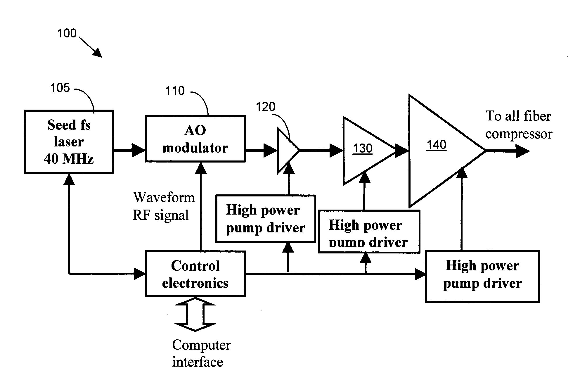
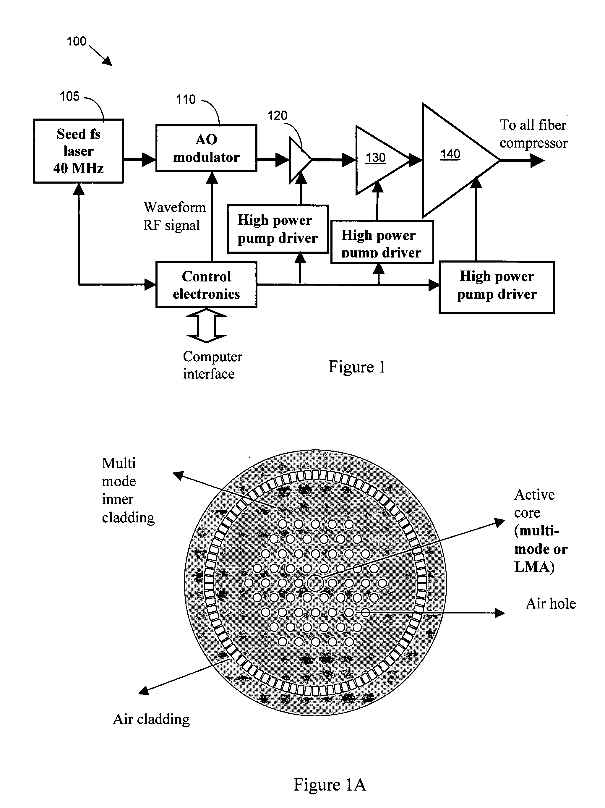
[0015]Referring to FIG. 1 for a schematic diagram of an mJ (millie-Joule) level femtosecond (fs) fiber laser system 100 of this invention. The laser system 100 includes a laser seed 105 for generating a seed laser. The seed laser 105 is a mode locked femtosecond fiber laser operating at 1060 nm spectral region and with a compressable pulse width of 100 fs and stretching into a few hundreds ps-10 ns pulse by a fiber stretcher (not shown) and projecting into an acoustic-optic (AO) modulator 110. The AO modulator 110 functions as a pulse picker for reducing the repetition rate from 40 MHz to 10's kHz to 100's kHz. The laser modulated by the AO modulator 110 is then projected to one low energy fiber amplifier 120 at a μJ level and a high energy fiber amplifier 130 at an energy of mJ level. Optionally, there may be two high-energy amplifiers. The higher energy amplifier 130 delivers an output power over 1 W and energy over 200 μJ femtosecond pulses. The amplified laser is then transmitte...


PUM


Abstract

A fiber Chirped Pulse Amplification (CPA) laser system includes a fiber mode-locking oscillator for generating a laser and stretching into a few hundreds ps-10 ns pulse by a fiber stretcher for projecting into an acoustic-optic (AO) functioning as a pulse picker for generated a modulated laser with a reduced repetition rate for projecting to a multiple stage amplifier. The multiple stage amplifier further includes a first high-energy amplifier implemented with a large mode area (LMA) fiber for amplifying the modulated laser up to a uJ level laser and a second amplifier implemented with a PCF based Yb doped fiber to further amplify the uJ level laser to a mJ level laser.

Description

[0001]This Formal application claims a Priority Date of Feb. 2, 2006 benefit from a Provisional Patent Application 60 / 765,599 filed by the one common Inventor of this application. The disclosures made in 60 / 765,599 are hereby incorporated by reference in this patent application.FIELD OF THE INVENTION[0002]The present invention relates generally to apparatuses and methods for providing fiber laser system. More particularly, this invention relates a system configuration for providing a practical approach to provide a femtosecond fiber laser with one mJ level of energy.BACKGROUND OF THE INVENTION[0003]Even though current technologies of fiber laser have made significant progress toward achieving a compact and reliable fiber laser system providing high quality output laser with ever increasing output energy, however those of ordinary skill in the art are still confronted with technical limitations and difficulties. Specifically, in a fiber laser system implemented with the Chirped Pulse...

Claims


Application Information

Patent Timeline
IPC IPC(8): H01S3/10
CPCH01S3/0057H01S3/06725H01S2301/08H01S3/06754H01S3/06729
Inventor LIU, JIAN
Owner POLARONYX
Why Eureka
Try Eureka