Frequency hopping control circuit for reducing EMI of power supplies

Active Publication Date: 2007-06-14
SEMICON COMPONENTS IND LLC
View PDF16 Cites 14 Cited by
  • Summary
  • Abstract
  • Description
  • Claims
  • Application Information

AI Technical Summary

Benefits of technology

[0013] Accordingly, the present invention is directed to provide a fre

Problems solved by technology

Even though the switching technology reduces the size of power supplies, the electric and magnetic interference (EMI) generated by a switching device has an impact on the power supply and the peripheral equipments thereof.
However, such kinds of apparatus increase power consumption, the cost and the size of power supplies.
However, a disadvantage of the conventional technologies is that the output of th

Method used


Image

  • Frequency hopping control circuit for reducing EMI of power supplies
  • Frequency hopping control circuit for reducing EMI of power supplies
  • Frequency hopping control circuit for reducing EMI of power supplies

Examples


Embodiment Construction

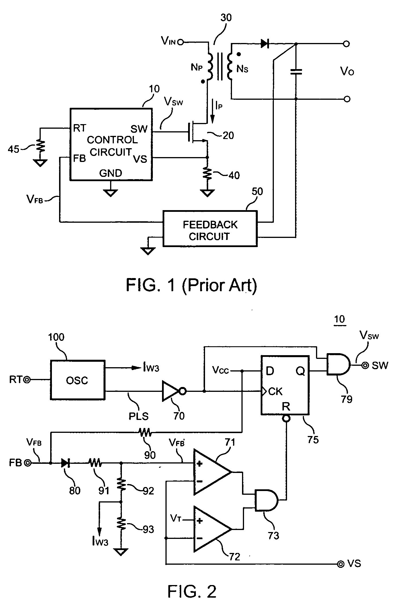
[0033]FIG. 1 illustrates a conventional power supply. A control circuit 10 is coupled to a feedback circuit 50 to generate a switching signal VSW for regulating an output of the power supply. The switching signal VSW is generated in response to a feedback signal VFB. The feedback circuit 50 is coupled to the output of the power supply to generate the feedback signal VFB. A switching current I of a transformer 30 is converted into a switching current signal VS by a sensing resistor 40. A switching current signal VS is provided to the control circuit 10 to generate the switching signal VSW.

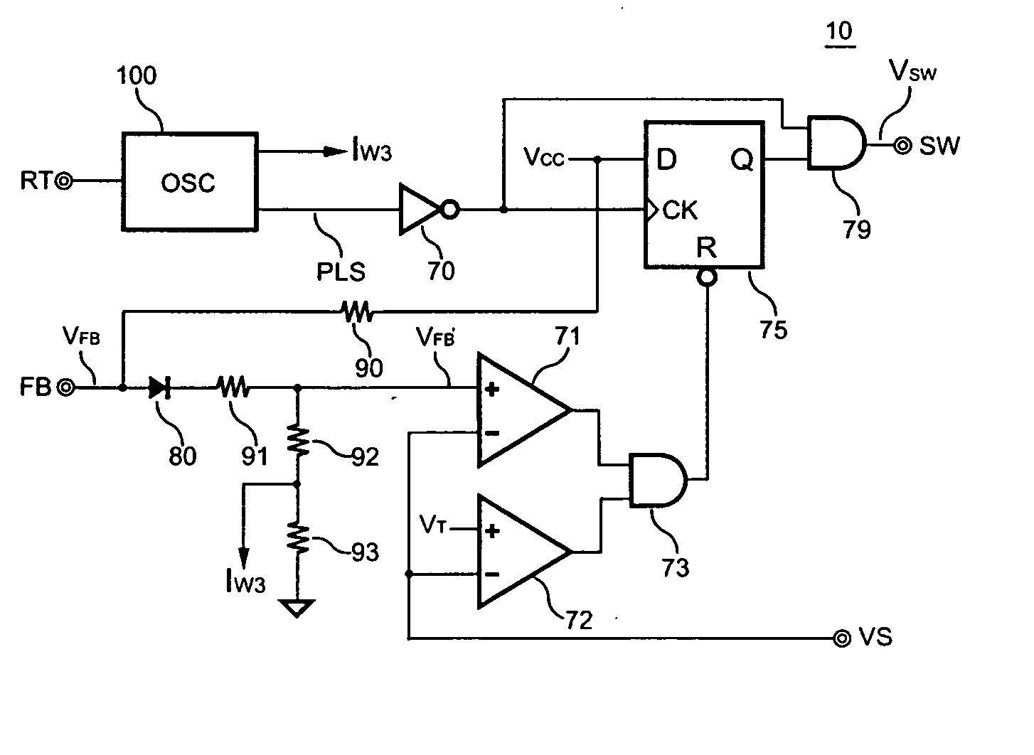
[0034]FIG. 2 is a circuit diagram illustrating the control circuit 10 according to an embodiment of the present invention. Referring to FIG. 2, in the control circuit 10, a switching circuit includes comparators 71 and 72, a flip-flop 75, an inverter 70, AND gates 73 and 79, a diode 80, a resistor 90, and an attenuator composed of resistors 91, 92, and 93. The resistor 90 is used for pulling up the...


PUM


Abstract

A control circuit having frequency hopping capability is used for reducing the EMI of a power supply. A switching circuit is coupled to a feedback circuit to generate a switching signal for regulating an output of the power supply. A first oscillator determines the switching frequency of the switching signal. A second oscillator is coupled to the first oscillator to modulate the switching frequency of the switching signal for reducing the EMI of the power supply. An output of the second oscillator controls the attenuation rate of the feedback signal of the feedback circuit. Therefore, even if the switching frequency is hopped, the output power and the output voltage can still be kept constant.

Description

BACKGROUND OF THE INVENTION [0001] 1. Field of the Invention [0002] The present invention relates to a power supply. More particularly, the present invention relates to the control circuit of a switching power supply. [0003] 2. Description of Related Art [0004] Power supplies are used for converting an unregulated power into a regulated voltage or current. FIG. 1 illustrates a conventional power supply. A control circuit 10 generates a switching signal VSW for controlling a transistor 20 to switch a transformer 30. A resistor 40 senses a switching current IP of the transformer 30 to control the switching. A resistor 45 determines the switching frequency of the control circuit 10. A terminal FB of the control circuit 10 is connected to an output of a feedback circuit 50. The feedback circuit 50 is coupled to an output terminal of the power supply to generate a feedback signal VFB. The duty cycle of the switching signal VSW is modulated in response to the feedback signal VFB to determ...

Claims


Application Information

Patent Timeline
IPC IPC(8): G05F3/00
CPCG05F1/562
Inventor YANG, TA-YUNG
Owner SEMICON COMPONENTS IND LLC
Why Eureka
Try Eureka