Apparatus and method for minimizing reception nulls in heterodyned ultrasonic signals

a heterodyned ultrasonic and signal technology, applied in the field of ultrasonic generators, can solve the problems of generating a higher ultrasonic energy level, faulty devices such as bearings, and too high in frequency to be heard by a human, so as to reduce the number of reception nulls, wide sensing

Inactive Publication Date: 2006-02-07
U E SYST
View PDF14 Cites 16 Cited by
  • Summary
  • Abstract
  • Description
  • Claims
  • Application Information

AI Technical Summary

Benefits of technology

[0019]The present inventors have determined that a heterodyned signal that drives a meter requires a relatively large dynamic range, but a limited frequency response, while a heterodyned signal that is required for headphones or spectral analysis may have a low dynamic range, but requires high resolution. Further, it has been found that the resolution or frequency response of the input transducer signal is degraded if a single heterodyning circuit is used to drive a number of circuits or meters with competing requirements. In order to overcome these competing requirements, the present invention uses a dual heterodyning circuit in which the two individual heterodyne circuits are separately optimized so that the second results in a signal with a large dynamic range and the first results in a signal with a great resolution, and neither unduly loads the transducer array or obscures subtle frequency components. This permits the capture of particularly low level frequency components for extraction during spectral analysis.
[0027]By using the focal point reflector with the dual heterodyning circuit of the present invention to provide the enhanced spectrum, it becomes easier to determine whether a detected resonance is mechanical or electrical. In addition, fault frequencies are also more easily discernable. In other words, the enhanced signal output having fewer reception nulls provides a lower signal-to-noise ratio, so as to increase the ease with which frequency components are analyzed.

Problems solved by technology

Additionally, faulty devices, such as bearings, generate a higher level of ultrasonic energy than do good bearings and thus, this condition can also be detected.
However, conventional means require two people to perform this procedure—one person to apply the lubricant to the device, and one person to operate the ultrasonic detector.
Since ultrasonic energy used for these purposes is generally in the range of 40 kHz, it is too high in frequency to be heard by a human being.
However, this attenuation method does not provide a way to establish fixed reference points to allow for repeatable measurements.
However, the detector disclosed in Peacock does not process the detected signal to produce an audible response, nor does it provide for signal attenuation after the initial pre-amplification stage.
It has been found, however, that with such an arrangement a typical transistor pre-amplifier loads the transducers to such an extent that the gains achieved by stacking them serially are lost.
Unfortunately, the transducers in this arrangement are not placed so that they both readily receive ultrasonic energy.
Thus, the Morris arrangement is not entirely satisfactory.

Method used


Image

  • Apparatus and method for minimizing reception nulls in heterodyned ultrasonic signals
  • Apparatus and method for minimizing reception nulls in heterodyned ultrasonic signals
  • Apparatus and method for minimizing reception nulls in heterodyned ultrasonic signals

Examples


Embodiment Construction

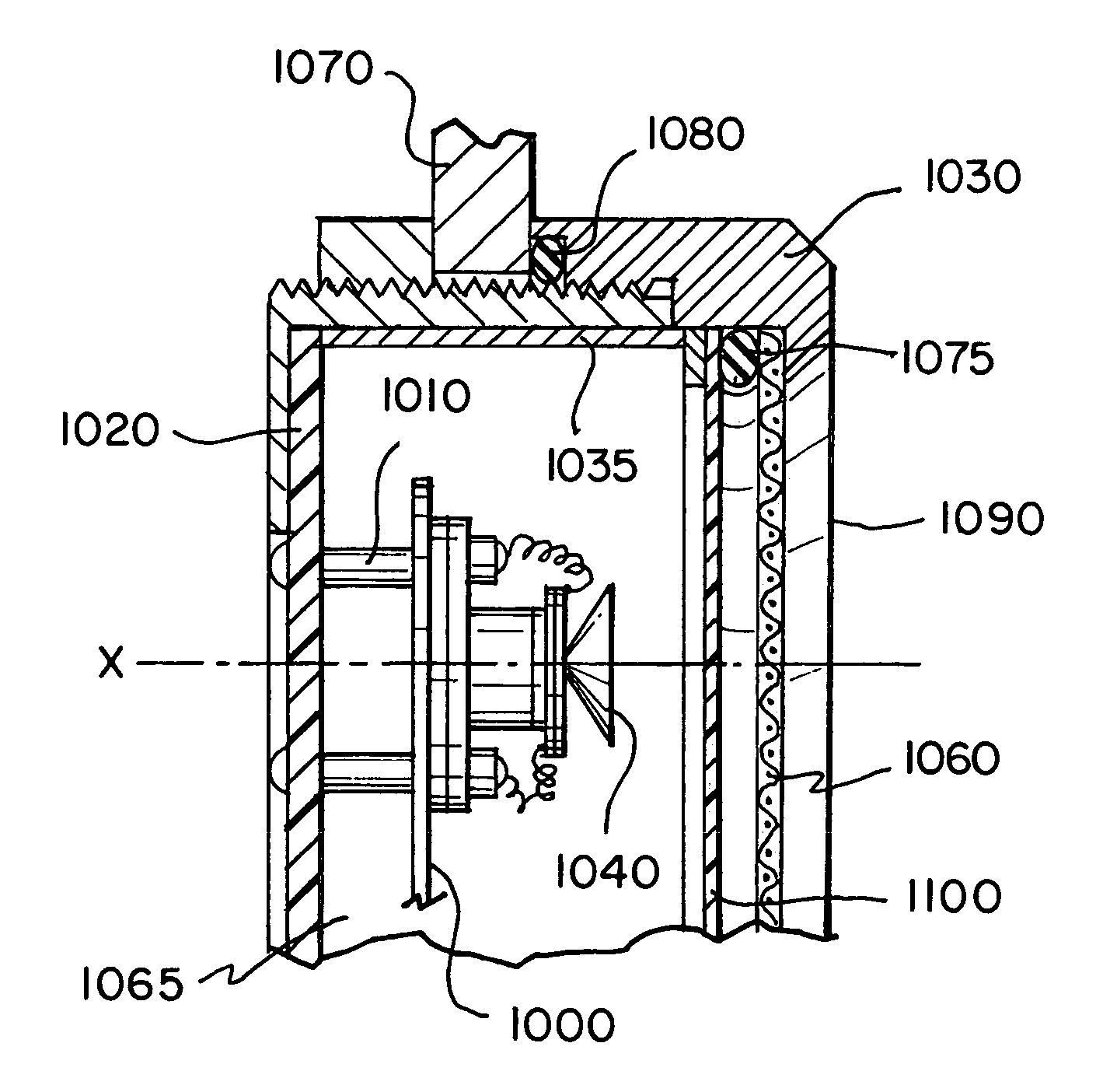
[0042]FIG. 6 is a perspective view of a portable ultrasonic detector 600. Toward the front of the housing there are ultrasonic transducers 95, as shown in FIG. 8. Micro-processor controlled circuits for heterodyning the ultrasonic signal to shift its frequency to the audio range are contained in the body of the housing. A display 82 is located at the back so the operation and the results can be viewed. At the back, there is also a jack 88 for headphones, so that the user can listen to the audio sound during a test, e.g., as a way of locating a leak. Other jacks and controls are located on the body or will be described subsequently.

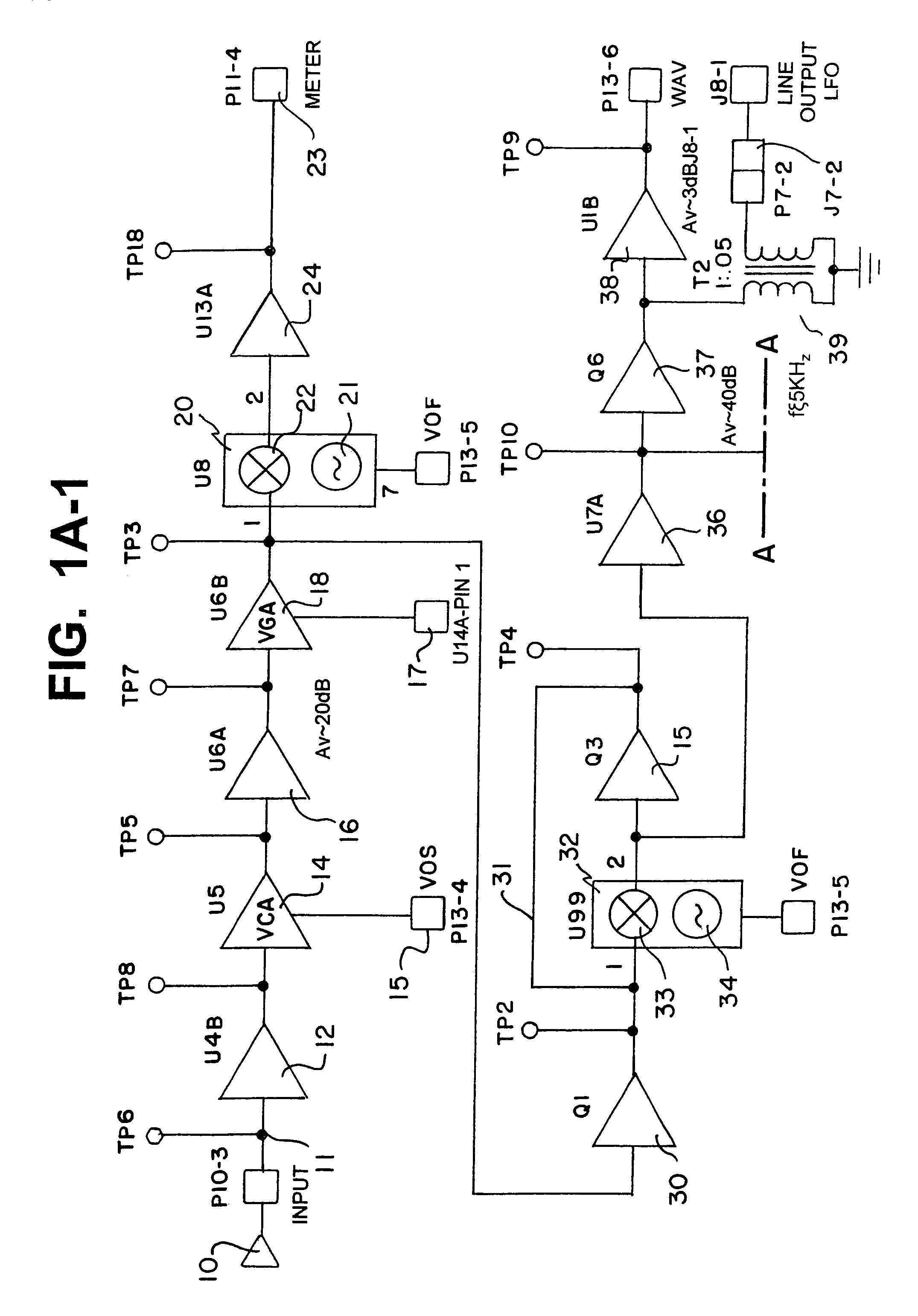
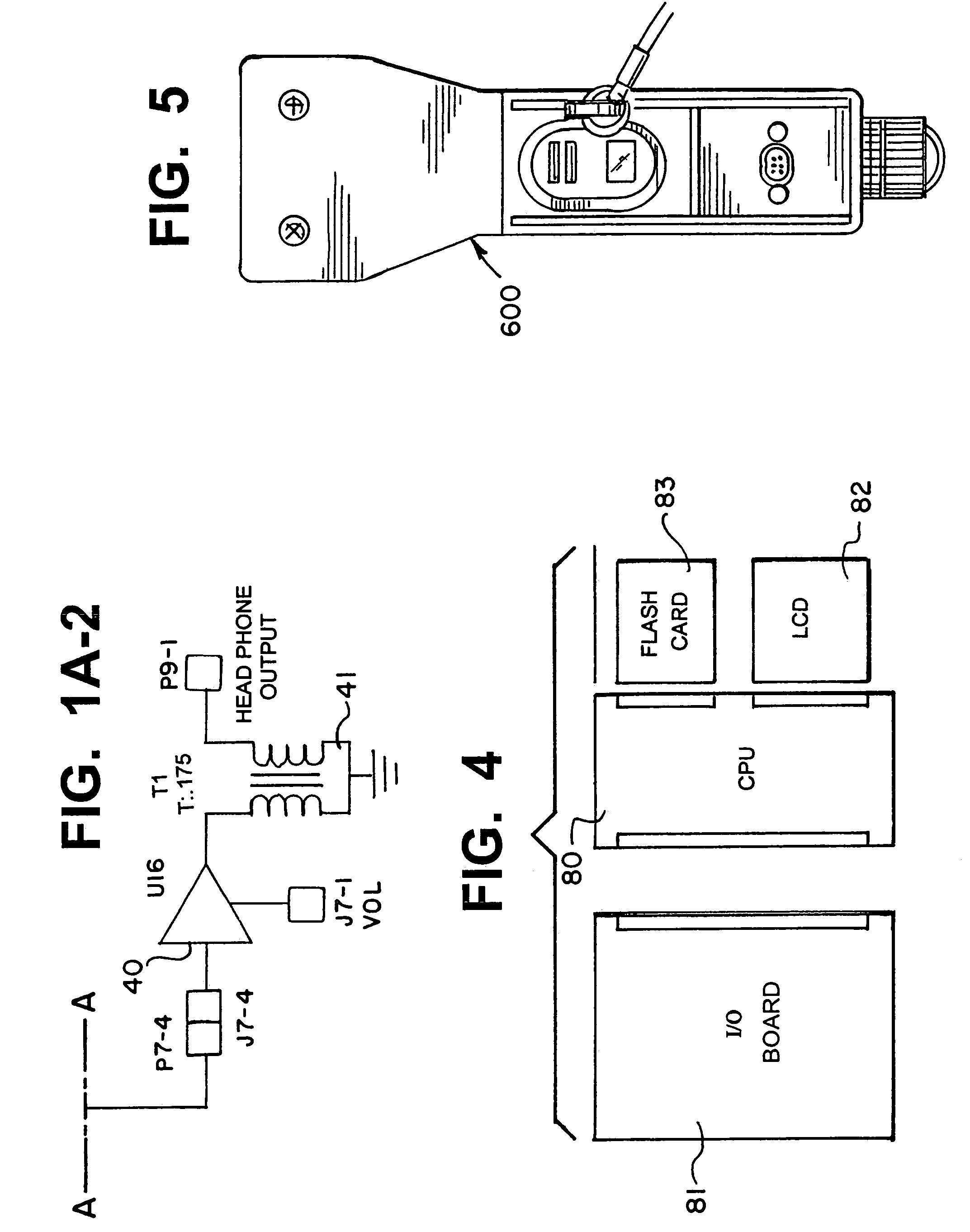
[0043]FIGS. 1A-1 and 1A-2 form an exemplary block diagram of the dual heterodyning circuit in accordance with the present invention which is located in the housing of the ultrasonic detector. In FIG. 1A-1, an input signal is applied from an ultrasonic transducer to a buffer amplifier 12 (U4B) at input 11 (P10). Typically, unity gain buffer 12 is used to ma...


PUM

PropertyMeasurementUnit
fixed angleaaaaaaaaaa
voltageaaaaaaaaaa

Abstract

A focal point reflector is used in conjunction with a dual heterodyne circuit to reduce reception nulls that can occur when performing ultrasonic measurements. The focal plane reflector is a flat non-porous or reflective material, such as printed circuit board (PCB) that is placed behind and in parallel with an ultrasonic array of piezoelectric transducers. In accordance with the invention, the addition of the focal point reflector to the array of piezoelectric array permits the reflection of ultrasonic energy that may “fall” between the crystals in the array and then back into the crystal elements.

Description

RELATED APPLICATIONS[0001]The present invention relates to, and is a Continuation in Part of, U.S. patent application Ser. No. 10 / 292,799, filed on Nov. 12, 2002, now U.S. Pat. No. 6,707,762 entitled System for Heterodyning an Ultrasonic Signal, which is incorporated herein by reference in its entirety.BACKGROUND OF THE INVENTION[0002]1. Field of the Invention[0003]The invention generally relates to the field of ultrasonic generators and, more particularly, to an apparatus and method for minimizing reception nulls in heterodyned ultrasonic signals.[0004]2. Description of the Related Art[0005]It is well known that ultrasonic generators and detectors can be used to locate leaks or defects, e.g., in pipes. Such a system is shown in U.S. Pat. No. 3,978,915 to Harris. In that arrangement, ultrasonic generators are positioned in a chamber through which the pipes pass. At the ends of these pipes, exterior to the chamber, ultrasonic detectors are located. At the point where a leak occurs in...

Claims


Application Information

Patent Timeline
Patent Type & Authority Patents(United States)
IPC IPC(8): H04R17/00H04R1/20G01M3/24G01N29/06G01N29/44G01N29/46
CPCG01M3/243G01N29/0609G01N29/46G01N29/44G01N2291/2634H04B11/00
Inventor GOODMAN, MARK A.BISHOP, WILLIAM
Owner U E SYST
Why Eureka
Try Eureka