
Hyper dispersion pulse compressor for chirped pulse amplification systems

a compressor and hyper-dispersion technology, applied in the field of ultra-short pulses, can solve the problems of not being able to arbitrarily increase, requiring large grating separations or extensive folding of optical paths, and not being able to achieve large grating separations, reducing system footprint, and reducing the footprint of pulse compressors

Active Publication Date: 2011-11-29
LAWRENCE LIVERMORE NAT SECURITY LLC
View PDF9 Cites 18 Cited by
  • Summary
  • Abstract
  • Description
  • Claims
  • Application Information

AI Technical Summary

Benefits of technology

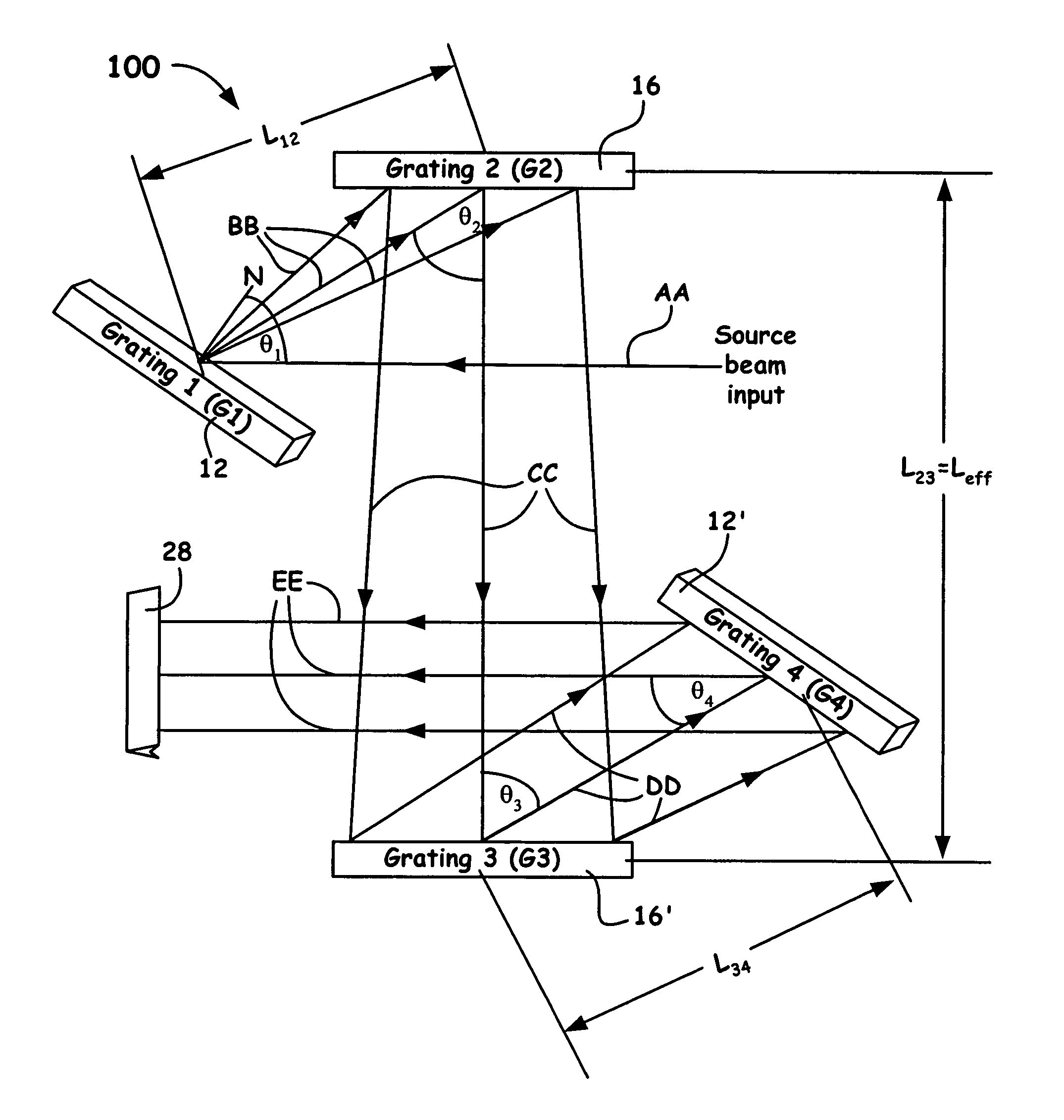
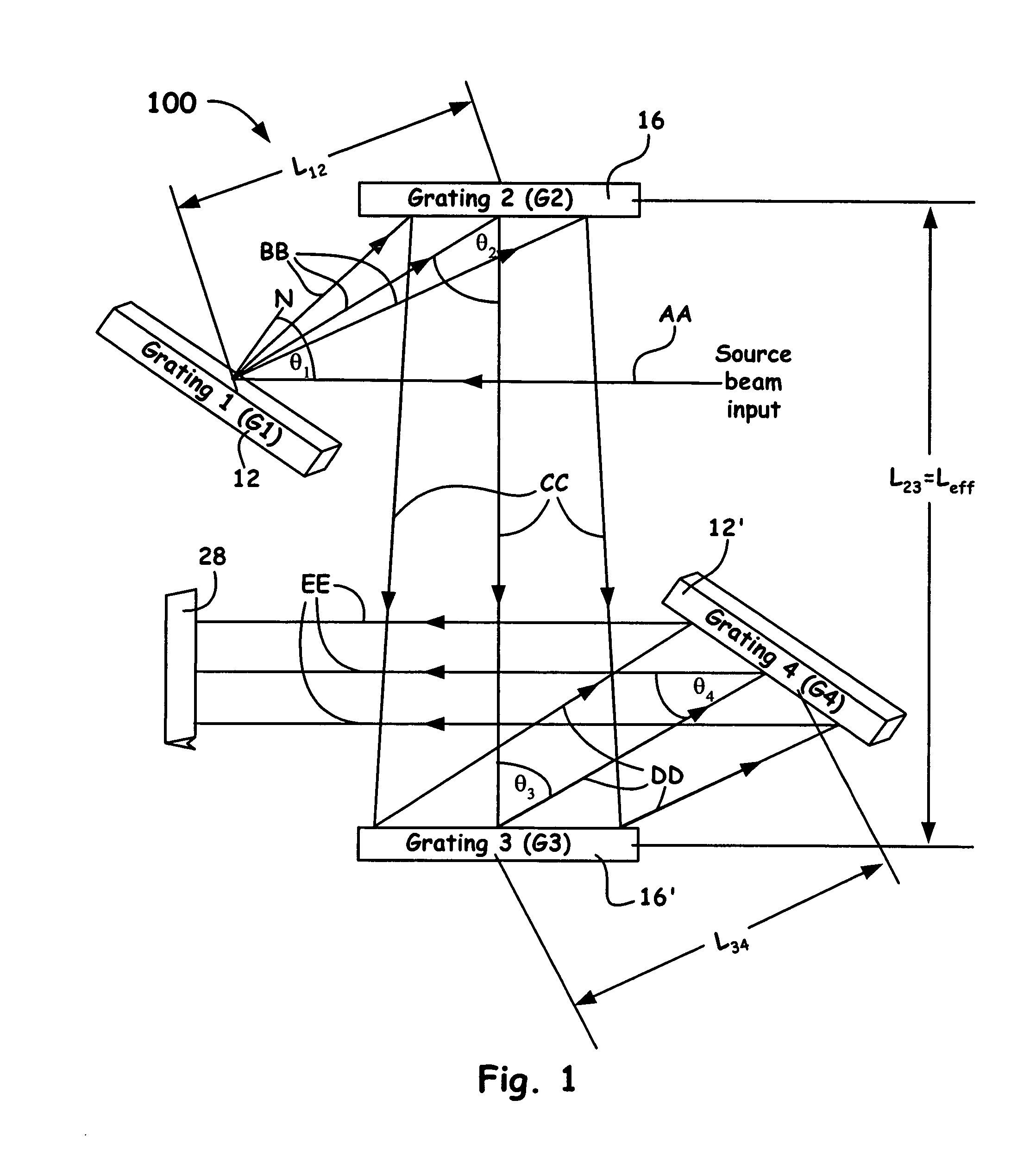
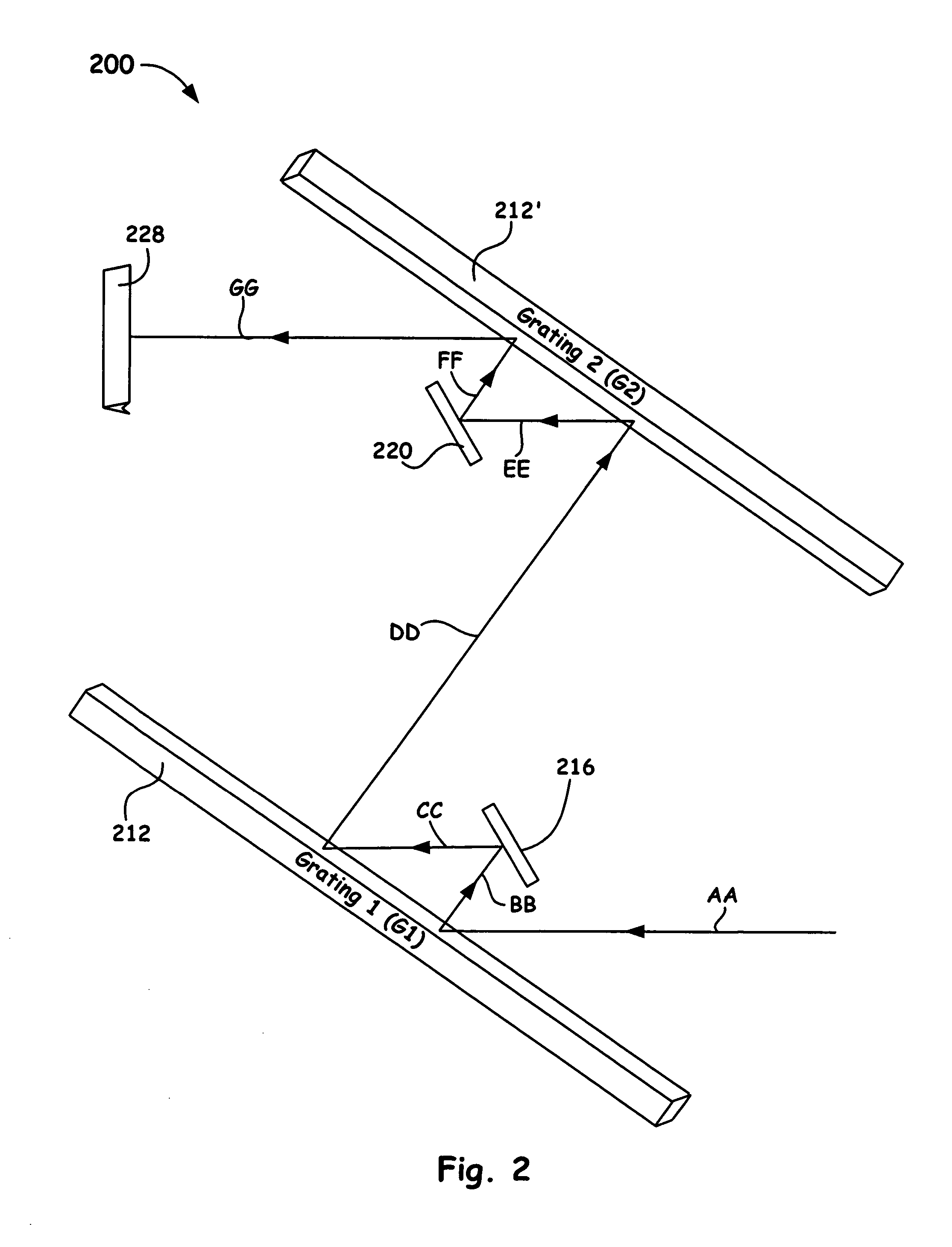
Accordingly, the present invention provides a laser pulse compressor that utilizes at least one efficient diffraction grating configured to disperse and amplify the angular dispersion of introduced frequency chirped pulses and configured to remove the frequency chirp from said pulses so as to compress temporally said one or more pulses and provide for a smaller compressor footprint.
Another aspect of the present invention provides a system method of compressing pulses that includes: receiving from a source one or more temporally stretched optical pulses having a predetermined frequency chirp, angularly dispersing the frequency content of the pulses; amplifying the angular dispersion of the one or more pulses; providing a collimated and spatially dispersed pulse spectrum of the amplified angularly dispersed frequency content of the one or more pulses; and passing the collimated and spatially dispersed pulse spectrum back through the system via an optical reflector so as to remove the spatial dispersed pulse spectrum, further reduce a system footprint and produce on or more predetermined temporally compressed pulses.
Accordingly, the present apparatus and method provide for arrangements that reduce the footprint of pulse compressors used in chirped pulse amplification (CPA) systems. Such arrangements enable the practical application of CPA configurations to common high-gain but narrow-bandwidth media such as, but not limited to, Nd:YAG and Nd:YLF, and greatly simplify the generation of transform-limited, e.g., about 1 ps to about 10 ps high-energy pulses, for precision micromachining, x-ray generation, lidar, gamma-ray generation, etc.

Problems solved by technology

For a given wavelength, however, the dispersion of a grating is a function of the groove density, which cannot be arbitrarily increased and still obtain a solution to the grating equation.
For CPA of pulses with transform-limited pulse widths in the picosecond regime, where the bandwidth of the pulse is low, grating compressors with grating separations of several meters are not uncommon, and prism compressors are impractical due to their even lower dispersion and greater length.
Even with grating-based compressors, application of CPA to materials such as Nd;YAG and Nd:YLF, whose bandwidth limits compressed pulse durations to of order of about 5 ps or greater requires impractically large grating separations or extensive folding of the optical path.

Method used


Image

  • Hyper dispersion pulse compressor for chirped pulse amplification systems
  • Hyper dispersion pulse compressor for chirped pulse amplification systems
  • Hyper dispersion pulse compressor for chirped pulse amplification systems

Examples


Embodiment Construction

Referring now to the following detailed information, and to incorporated materials; a detailed description of the invention, including specific embodiments, is presented.

Unless otherwise indicated, numbers expressing quantities of ingredients, constituents, reaction conditions and so forth used in the specification and claims are to be understood as being modified by the term “about.” Accordingly, unless indicated to the contrary, the numerical parameters set forth in the specification and attached claims are approximations that may vary depending upon the desired properties sought to be obtained by the subject matter presented herein. At the very least, and not as an attempt to limit the application of the doctrine of equivalents to the scope of the claims, each numerical parameter should at least be construed in light of the number of reported significant digits and by applying ordinary rounding techniques. Notwithstanding that the numerical ranges and parameters setting forth the...


PUM

PropertyMeasurementUnit
incidence angleaaaaaaaaaa
exit angleaaaaaaaaaa
reflectivityaaaaaaaaaa

Abstract

A grating pulse compressor configuration is introduced for increasing the optical dispersion for a given footprint and to make practical the application for chirped pulse amplification (CPA) to quasi-narrow bandwidth materials, such as Nd:YAG. The grating configurations often use cascaded pairs of gratings to increase angular dispersion an order of magnitude or more. Increased angular dispersion allows for decreased grating separation and a smaller compressor footprint.

Description

BACKGROUND OF THE INVENTION1. Field of the InventionThe present invention provides ultra-intense laser pulses capable of interacting with matter, and more specifically, it relates to a chirped pulse amplification system and a method that includes lengthening a pulse's duration by often using cascaded pairs of gratings so as to increase the angular dispersion and produce a high power, short pulse.2. Description of Related ArtThe conventional method for circumventing optical damage due to amplification of high intensity pulsed sources is accomplished by chirped pulse amplification (i.e., CPA).Chirped pulse amplification originated 60 years ago during the development of microwave radar. In the optical case, one avoids intensity-dependent damage by increasing the input temporal pulse duration prior to amplification by passing an input pulse through a frequency-dependent delay line. Such a dispersive delay line often includes prisms or gratings to separate the spectral content of the pul...

Claims


Application Information

Patent Timeline
Patent Type & Authority Patents(United States)
IPC IPC(8): H01S3/10
CPCH01S3/0057
Inventor BARTY, CHRISTOPHER P. J.
Owner LAWRENCE LIVERMORE NAT SECURITY LLC
Learn More