Dielectric-coating structure reflecting mirror used for chirp pulse amplification optical spectrum shaping

A spectral shaping, chirped pulse technology, applied in mirrors, lasers, laser parts and other directions, can solve the problems of inapplicability, complex adjustment, unsuitable neodymium glass system, etc., to achieve the effect of strong versatility and low cost

Inactive Publication Date: 2008-03-12
SICHUAN UNIV +1
View PDF0 Cites 19 Cited by
  • Summary
  • Abstract
  • Description
  • Claims
  • Application Information

AI Technical Summary

Problems solved by technology

[0004] It can also be seen from the above documents that the international general method mainly has the following shortcomings: 1. Adding a tunable air-gap etalon to the regenerative amplifier to adjust the spectrum, but this adjustment is more complicated, and in the Shenguang II kilojoule petawatt high-power amplification system In the optical parametric chirped pulse amplification technique (OPCPA) is used to replace the regenerative amplifier, so it is not applicable
But this approach is not practical for systems beyond the terawatt level
3. The long-wavelength injection method makes the gain narrowing benefit to compensate for the saturation effect, but this method also affects the stability of the system
However, the color resolution of AOPDF can only be used for broadband chirped pulse systems such as titanium sapphire, and is not suitable for neodymium glass systems.

Method used


Image

  • Dielectric-coating structure reflecting mirror used for chirp pulse amplification optical spectrum shaping
  • Dielectric-coating structure reflecting mirror used for chirp pulse amplification optical spectrum shaping
  • Dielectric-coating structure reflecting mirror used for chirp pulse amplification optical spectrum shaping

Examples


Embodiment 1

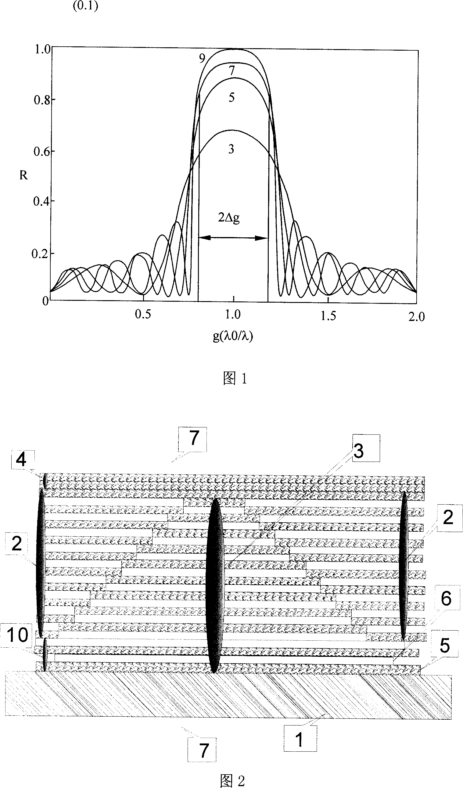
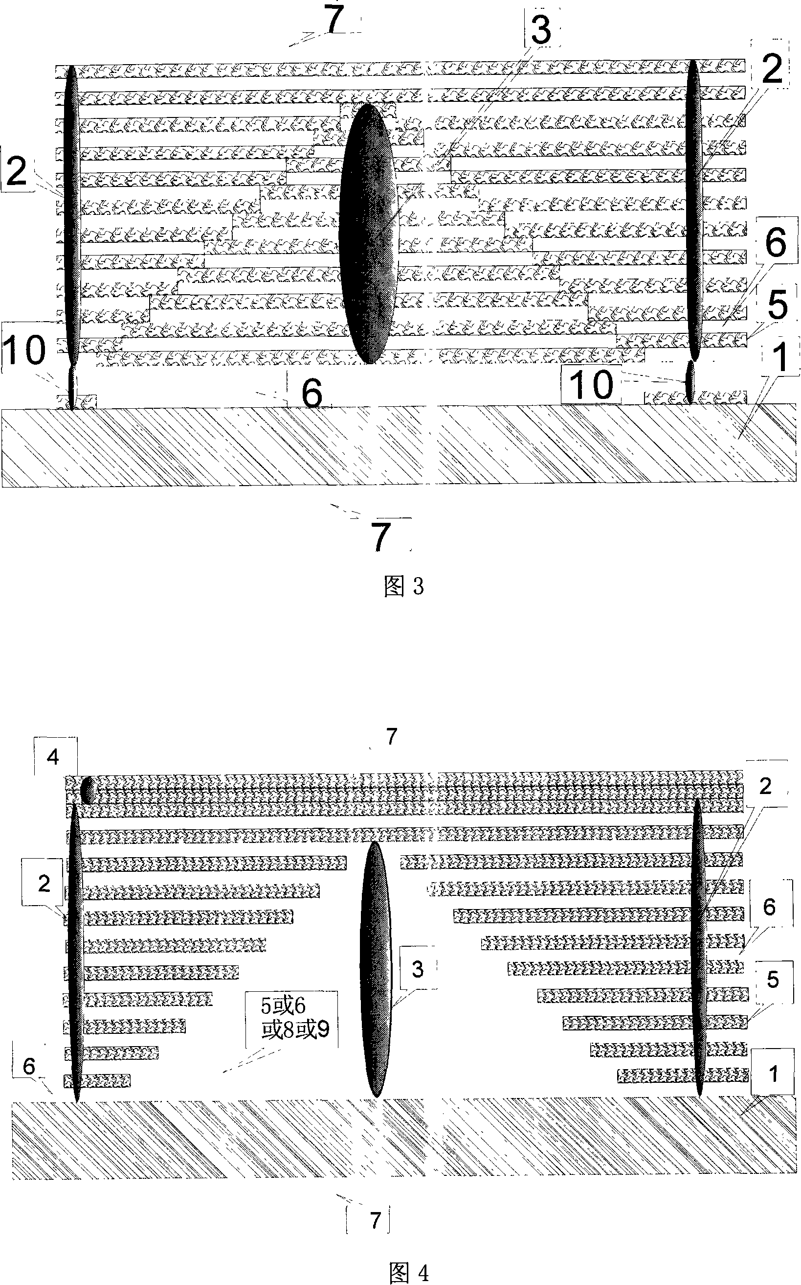
[0054] Under the outer protective layer 4 provided on the transparent substrate 1, and the high-reflection medium film system 2 composed of high-refractive-index medium film layers 5 and low-refractive-index medium film layers 6 alternately, a high-transmittance film system is buried, and the Specially designed anti-reflection coatings, such as λ 0 / 4 anti-reflection standard film system. Then etch and polish the micro-relief structure on the anti-reflection film system or film stack. Using mask technology, then plate high reflective dielectric film system 2 as the standard λ 0 / 4 high reflection film system, since the reflection phase is required to be unchanged, the coating steps are required to be accurately aligned vertically and horizontally. The role of the outer guiding protective layer is mainly to protect against scratches and the influence of atmospheric water vapor. At the same time, the outer guiding protective layer is thick because the λ / 2 layer is actually a ...

Embodiment 2

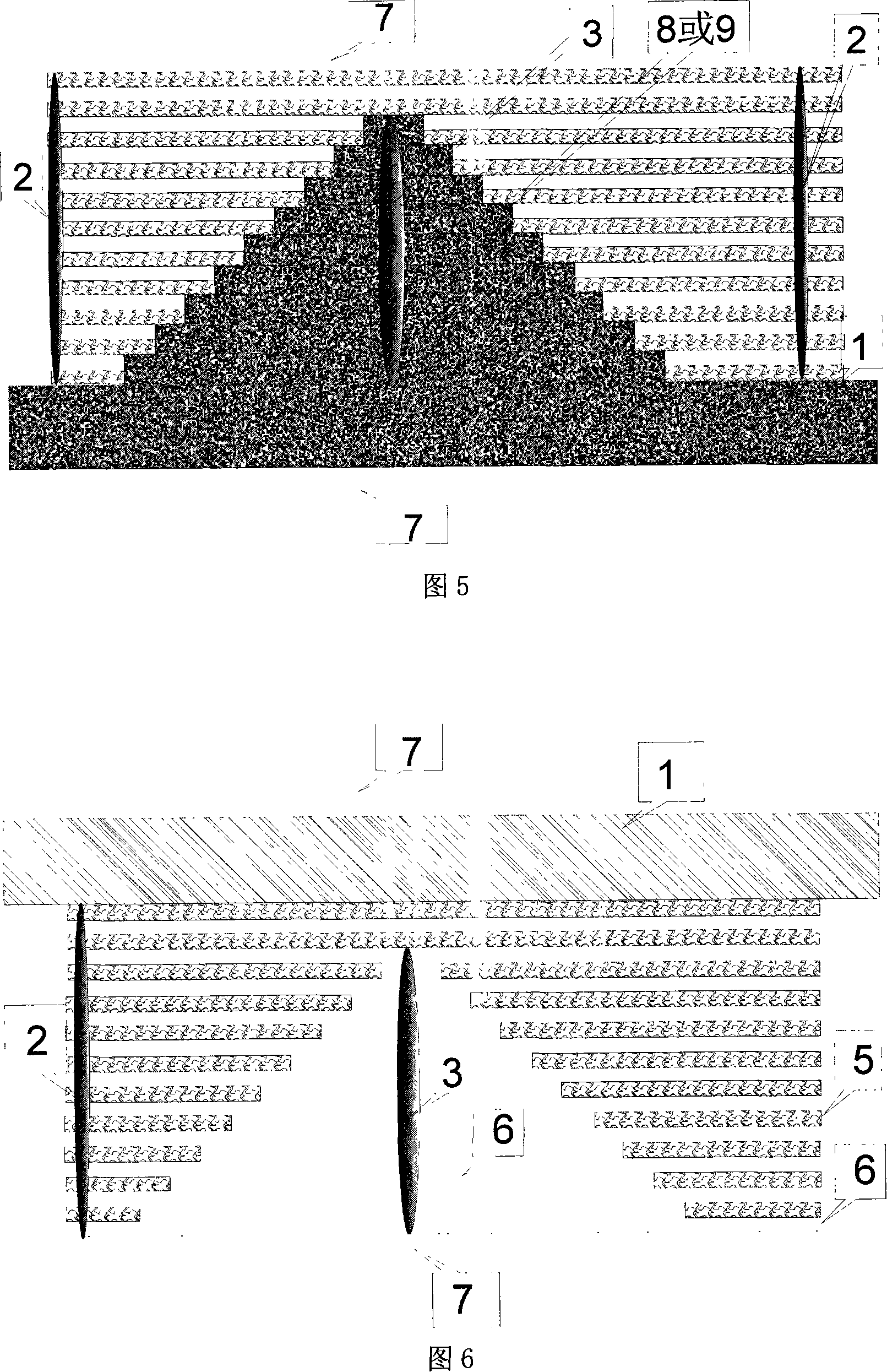
[0056] There may also be no outer guiding protective layer 4 on the transparent substrate 1, and a specially designed anti-reflection film system may be directly plated in advance, and the anti-reflection film system is λ 0 / 4 anti-reflection standard film system, and then etch and polish the micro-relief structure on the anti-reflection film system or film stack. Utilize the mask technology, and then plate the highly reflective dielectric film system 2 as the usual standard λ 0 / 4 High reflection film system, because the reflection phase is required to be unchanged, so the coating steps are required to be accurately aligned vertically and horizontally. The guiding film layer 10 is a λ / 2 transparent layer composed of the low-refractive-index dielectric film layer 6, but it has a selective effect on other wavelengths and can be used to improve the bandwidth characteristics of the dielectric film. As shown in Figure 3. When the high-power laser chirped pulse of the plane wave ...

Embodiment 3

[0058] On the transparent substrate 1 , there is an outer guide protection layer 4 , and a high-reflection medium film system 2 composed of alternating high-refractive-index medium film layers 5 and low-refractive-index medium film layers 6 , and a transparent medium micro-relief structure 3 is embedded. The transparent medium is specially designed by pre-plating, and the material can be a high refractive index medium 5, or a low refractive index medium 6, or a glass medium 8, or a semiconductor medium 9, or an air medium 7, but due to the thermal coefficient of the gas, it is generally not in the film Use 7 in layer. Then etch and polish the micro-relief structure 3 on the transparent medium. Utilize the mask technology, and then plate the highly reflective dielectric film system 2, such as the usual standard λ 0 / 4 High reflection film system, because the reflection phase is required to be unchanged, so the coating steps are required to be accurately aligned vertically and ...


PUM


Abstract

The present invention relates to a chirp pulse amplifying spectrum shaping dielectric film structure reflector, which comprises a transparent substrate, a high reflectance film system, an anaglyph structure and an external protective layer. Wherein, the high reflectance film system is composed of a plurality of staggered dielectric films. A high reflectance film layer and a lower reflectance film layer of the high reflectance film closely contact the anaglyph structure. The anaglyph structure can take a plurality of shapes, such as a micro-lens high transparency film system structure, an air dielectric structure, a glass anaglyph structure or other transparent dielectric structures, including semiconductor structures. As a high-power laser chirp pulse with a plane wave structure vertically casts onto the reflector, the laser passes through the high reflectance film system and the anaglyph structure and all residual lasers are reflected to back of the reflector through the transparent substrate. Reflex intensity distribution is modulated to a needed spectrum distribution structure. The reflector of the present invention can be inserted into any place of an amplifier link and improve capacity to distinguish shaping spectrum chromatic dispersion to a certain level. Scope modulation exceeds 60% without changing phase position, thus adapting to PW devices.

Description

technical field [0001] The invention relates to a dielectric film reflector, in particular to a novel reflector with a multi-layer dielectric film structure used for high-power laser chirped pulse amplification for modulating spectrum shaping. Background technique [0002] In the research of ICF inertial confinement nuclear fusion, the physical experiment has very strict requirements on the pulse parameters of the high-power laser output, and in the design of the Shenguang II kilojoule petawatt high-power amplification system, the problem that people care about is to modulate the corresponding pulse Spatio-temporal characteristics and spectral characteristics, in which the modulated spectral shaping of the chirped pulse is mainly to eliminate the influence of the gain narrowing effect and the gain saturation effect in the chirped pulse amplification as much as possible. Such as literature: [0003] Zhang Bin, Lu Baida, "The Inverse Problem of Multistage and Multipass Pulse ...

Claims


Application Information

Patent Timeline
Patent Type & Authority Applications(China)
IPC IPC(8): G02B5/08H01S3/00
Inventor 李铭张彬戴亚平范正修王韬黄伟
Owner SICHUAN UNIV
Why Eureka
Try Eureka