Binding equipment for textile industry

A technology of binding equipment and industry, applied in the field of binding equipment for clothing sign binding, can solve the problems of increased cost, low production efficiency, inconvenient use, etc., and achieves the effect of convenient layout and cost saving

Inactive Publication Date: 2009-06-10
上海允科自动化有限公司
View PDF0 Cites 15 Cited by
  • Summary
  • Abstract
  • Description
  • Claims
  • Application Information

AI Technical Summary

Problems solved by technology

At present, the tag binding machine commonly used in the factory uses three cylinders as the power source to perform three linear actions to complete the three processes of compressing clothes, steel needle movement and rubber needle extrusion. Due to the limitation of the air source, this This kind of binding machine is generally fixed at one position. When binding the tag, the clothes need to be moved to the fixed position, which greatly increases the labor intensity, low production efficiency, inconvenient use, and requires special air supply equipment, which increases the cost.

Method used


Image

  • Binding equipment for textile industry

Examples


Embodiment Construction

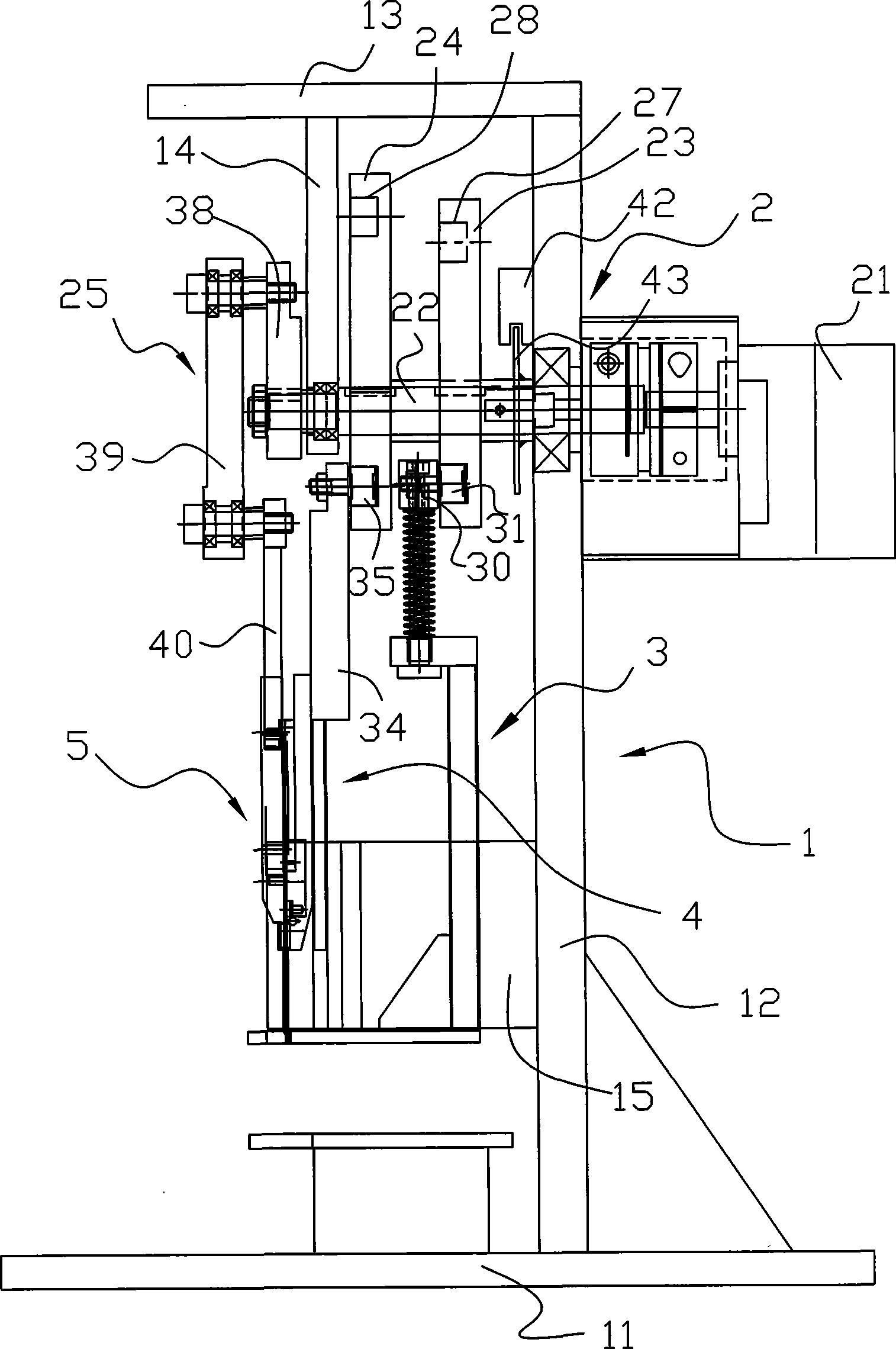
[0016] The binding equipment for the textile industry of the present invention will be further described below in conjunction with the accompanying drawings and specific embodiments.

[0017] Such as figure 1 As shown, the binding device of the present invention includes a frame 1 , a power mechanism 2 , a pressing mechanism 3 , a steel needle moving mechanism 4 and a glue needle extruding mechanism 5 .

[0018] The frame 1 includes a base 11 , a vertical plate 12 , a horizontal beam 13 , a hanging plate 14 and a guide frame 15 . The base 11 is a horizontal plate, the vertical plate 12 is fixed on the base 11, the horizontal beam 13 is horizontally fixed on the top of the vertical plate 12, and the hanging plate 14 is fixed on the lower end surface of the horizontal beam 13 at an interval of one end from the vertical plate 12. Rail frame 15 is fixed on the middle part of vertical plate 12.

[0019] The compression mechanism 3, the steel needle movement mechanism 4 and the ru...


PUM


Abstract

The invention relates to binding equipment in the textile industry, which comprises a frame, an actuating unit, a hold-down mechanism, a steel needle movement mechanism and a plastic pin extruding mechanism, wherein the hold-down mechanism, the steel needle movement mechanism and the plastic pin extruding mechanism which are connected to the actuating unit are driven by the actuating unit to reciprocate up and down along a guide rail on a guide rail support of the frame; and the actuating unit is fixed on the frame. The binding equipment is characterized in that the actuating unit is an electric mechanism. The equipment is suitable for binding clothes, shoes and hats, and socks in families or individual workshops, and can be used for binding hangtags or a plurality of pairs of socks. The equipment is suitable for binding products with different thicknesses, and can bind plastic pins with different specifications through adjustment. The equipment is operated by means of driving two cams and a connecting rod by a motor, and changes the phenomenon that the prior equipment realizes binding through three cylinders. The binding equipment has the advantages of no air source limitation tooperation places and simple and reliable operation.

Description

technical field [0001] The present invention relates to a kind of binding equipment used in garment processing, more particularly relates to a kind of binding equipment of garment label binding. Background technique [0002] In the textile industry, after the finished product is completed, before the finished product is packaged, it is necessary to bind and hang the finished product. The binding tag mainly includes three movement processes. One is to compress the clothes, that is, to compress the clothes or socks to be bound, so as to fix them and facilitate the subsequent binding. The second is the steel needle movement, that is, the hollow steel needle penetrates the compressed clothes. The third is to press out the rubber needle, that is, to press the rubber needle into the clothing along the inside of the steel needle and along the opening on one side of the steel needle. At present, the tag binding machine commonly used in the factory uses three cylinders as the power...

Claims


Application Information

Patent Timeline
Patent Type & Authority Applications(China)
IPC IPC(8): B65C7/00B65C5/06
Inventor 柯恩清王东
Owner 上海允科自动化有限公司
Why Eureka
Try Eureka