Substrate holder, substrate conveying device and substrate processing system
A substrate processing system and substrate retention technology, applied in thin material processing, furnace components, electrical components, etc., can solve problems such as difficulties, achieve long life, prevent particles, and prevent damage
- Summary
- Abstract
- Description
- Claims
- Application Information
AI Technical Summary
Problems solved by technology
Method used
Image
Examples
no. 1 approach
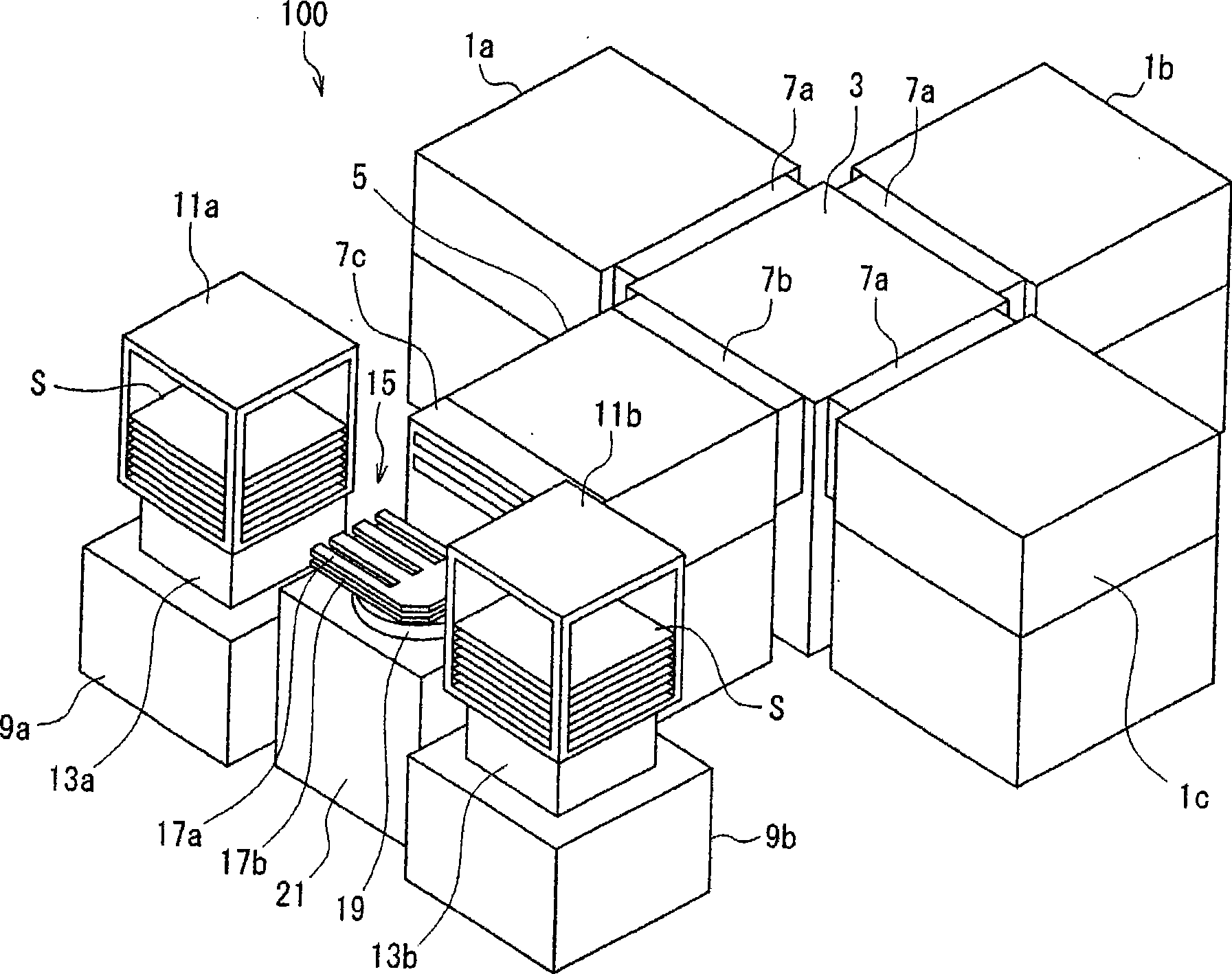
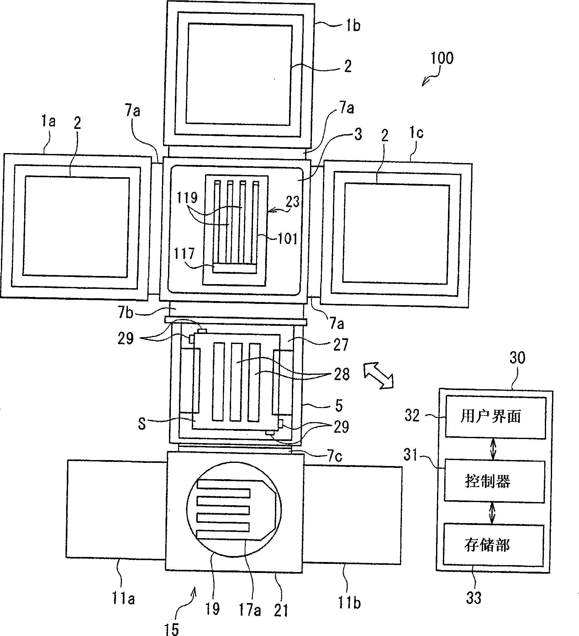
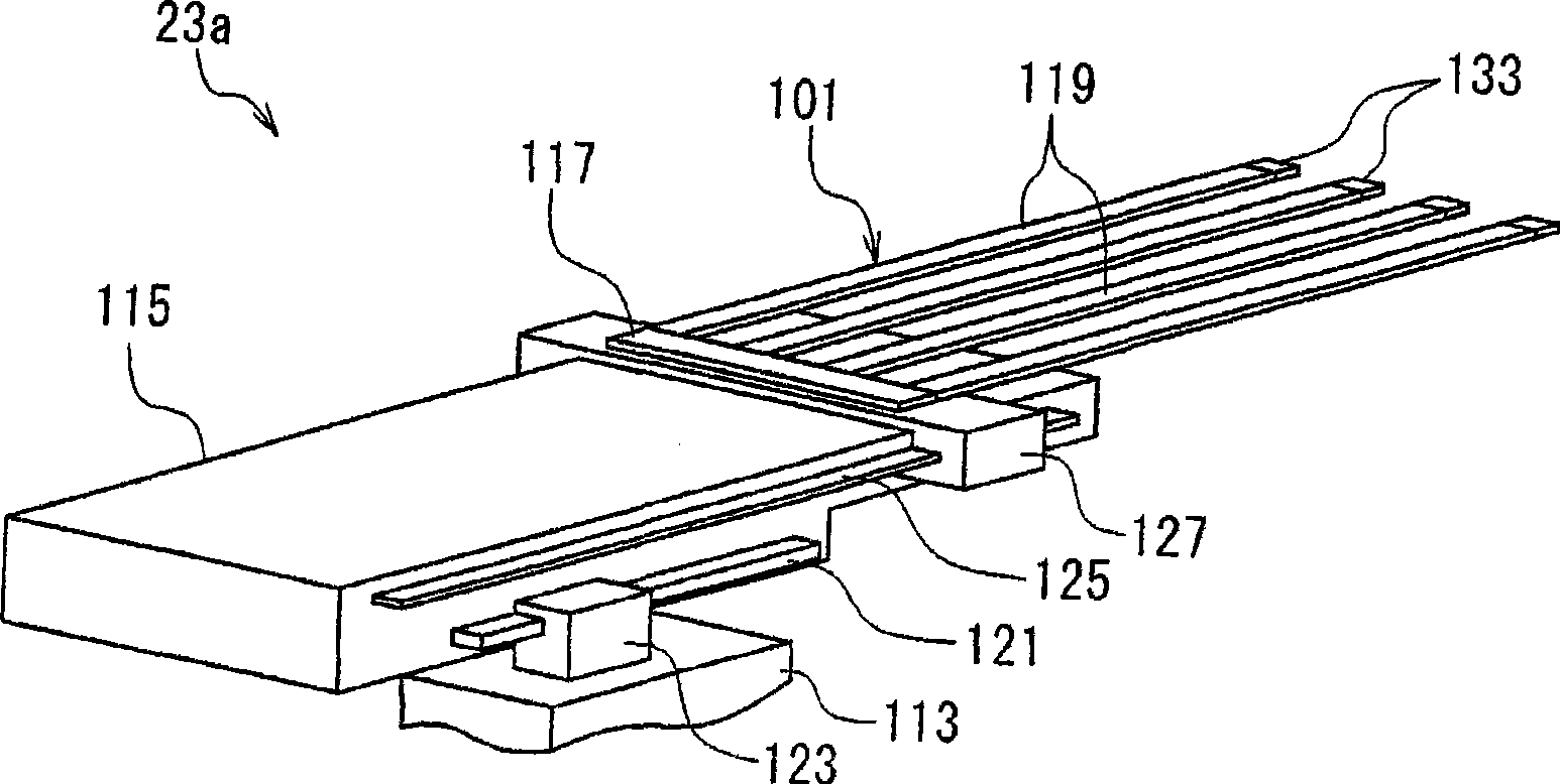
[0049] Hereinafter, embodiments of the present invention will be described in detail with reference to the drawings. Here, a substrate transfer device including the substrate holder according to the first embodiment of the present invention and a substrate processing system including the substrate transfer device will be described as examples. figure 1 is a perspective view briefly showing a vacuum processing system 100 as a substrate processing system; figure 2 It is a plan view schematically showing the inside of each chamber. The vacuum processing system 100 has a multi-chamber structure having a plurality of processing chambers 1a, 1b, and 1c. The vacuum processing system 100 is configured as a processing system for performing plasma processing on, for example, a glass substrate (hereinafter, simply referred to as "substrate") S for FPD. Among these, examples of the FPD include a liquid crystal display (LCD), an electroluminescence (Electro Luminescence: EL) display, a ...
no. 2 approach
[0086] Image 6 Shown is the cross-sectional structure of the front end portion supporting the pickup 119 of the fork 101 according to the second embodiment of the present invention. In the present embodiment, the cap body 139 has a main protector 139a mainly absorbing impact along the X direction and an insertion part 139b protruding from the main protector 139a, and has a convex cross section. However, in the following description, differences from the first embodiment will be mainly described, and the same reference numerals will be attached to the same components as those in the first embodiment, and descriptions thereof will be omitted.
[0087] The insertion part 139b which is a part of the cap body 139 is inserted into the front-end|tip part of the main body 131 which supports the pickup 119, and is attached. The cap body 139 is used to protect the front end of the support picker 119 from impact when it comes into contact with a chamber wall or the like which is a syst...
no. 3 approach
[0092] Figure 7 It shows the cross-sectional structure of the front-end|tip part of the support picker 119 of the fork which concerns on 3rd Embodiment of this invention. In this embodiment, if Figure 7 As shown, the cap body 141 has a main protection portion 141a mainly for absorbing impact along the X direction, and a wall-shaped covering portion 141b formed substantially at right angles on the main protection portion 141a, and has a concave cross section. The covering part 141b which is a part of the cap body 141 is attached so that it may cover the periphery of the front-end vicinity of the main body 131 which supports the pickup 119. As shown in FIG.
[0093] The cap body 141 is used to protect the front end of the main body 131 supporting the pickup 119 from impact when it comes into contact with a chamber wall or the like which is a system component in the substrate processing system 100 . In addition, in the cap body 139, since the surroundings near the front end o...
PUM
| Property | Measurement | Unit |
|---|---|---|
| Young's modulus | aaaaa | aaaaa |
| Young's modulus | aaaaa | aaaaa |
| Young's modulus | aaaaa | aaaaa |
Abstract
Description
Claims
Application Information
 - R&D
- Intellectual Property
- Life Sciences
- Materials
- Tech Scout
- Unparalleled Data Quality
- Higher Quality Content
- 60% Fewer Hallucinations
Browse by: Latest US Patents, China's latest patents, Technical Efficacy Thesaurus, Application Domain, Technology Topic, Popular Technical Reports.
© 2025 PatSnap. All rights reserved.Legal|Privacy policy|Modern Slavery Act Transparency Statement|Sitemap|About US| Contact US: help@patsnap.com


