

One-way clutch
A one-way clutch, circumferential direction technology, applied in one-way clutches, clutches, mechanical equipment and other directions, can solve the problems of difficult opening edge 7b, increase manufacturing cost, reduce product yield and other problems, achieve good reproducibility, reduce costs, The effect of preventing shedding
- Summary
- Abstract
- Description
- Claims
- Application Information
AI Technical Summary
Problems solved by technology
Method used
Image

Examples
Embodiment Construction
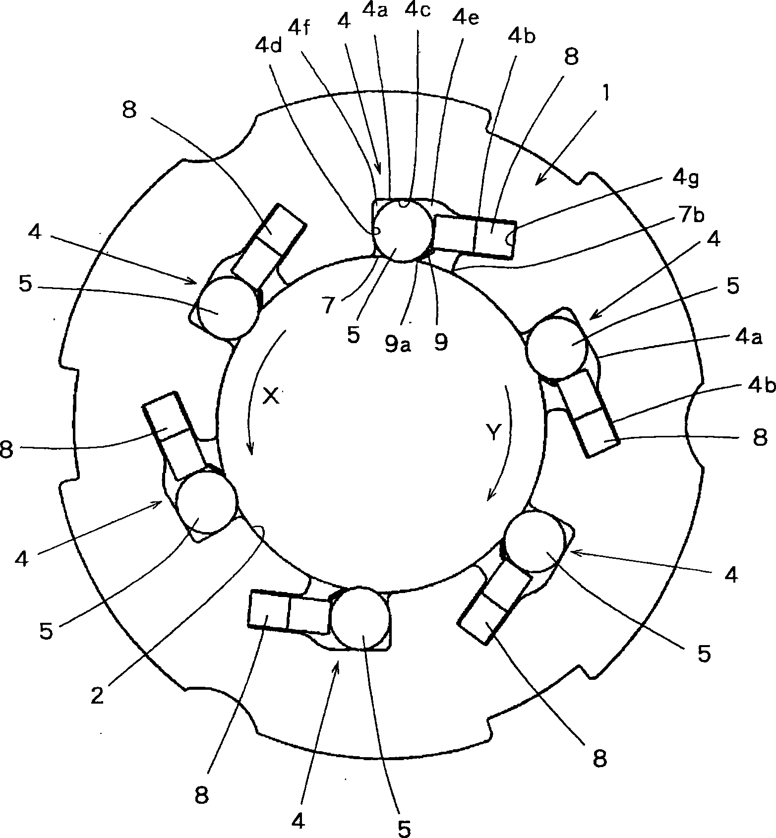
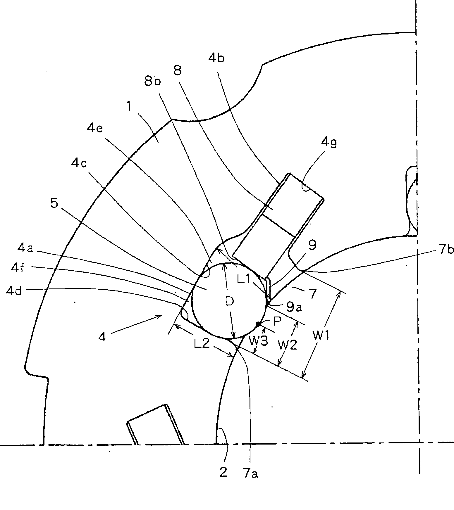
[0056] Figure 1 to Figure 5 In the shown one-way clutch of the first embodiment, a shaft hole 2 is formed in a housing 1 , and a plurality of needle roller holding spaces 4 are formed along the shaft hole 2 . The needle roller holding space 4 is constituted by a needle roller holding portion 4a into which the needle roller 5 which is a rolling member of the present invention is inserted, and a spring holding portion 4b into which the spring member 8 is inserted. In addition, the needle roller holding space 4 has a wide portion 4e and a narrow portion 4f. In this wide portion 4e, the relative distance between the outer periphery of the shaft inserted into the shaft hole 2 and the facing surface 4c is larger than the outer diameter D of the needle roller 5, while in the narrower portion 4f, it is smaller than the outer diameter D. .
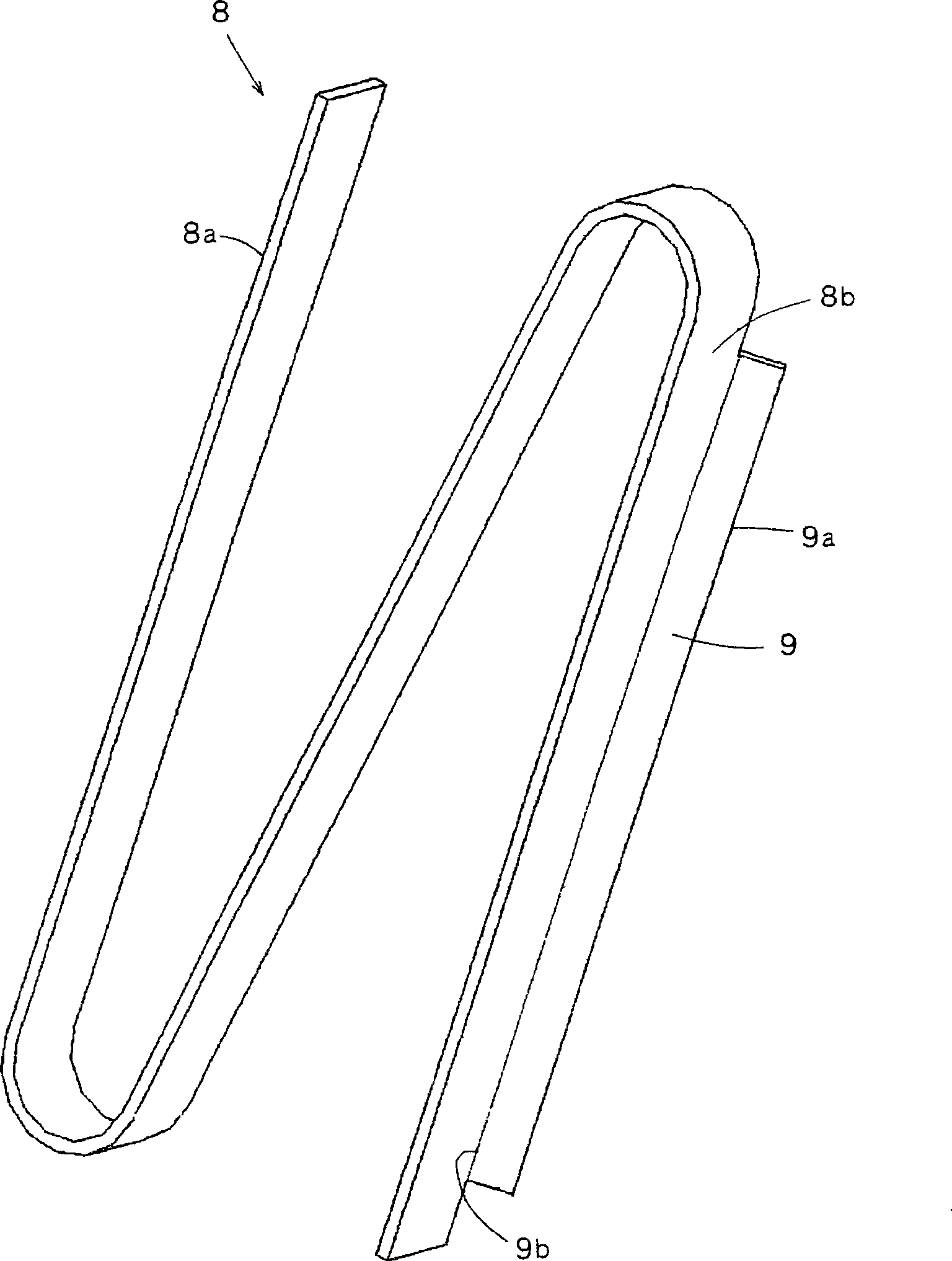
[0057] The spring member 8 used in the first embodiment is as image 3 The S-shaped metal leaf spring shown has a base end surface 8a that con...
PUM
 Abstract
Description
Claims
Application Information