Exact crack width detecting method

A technology of crack width and detection method, which is applied in the direction of measuring devices, instruments, and optical devices, etc., can solve the problems of observation result error, misidentification, and enlargement, and achieve the effect of safe detection and reliability and improvement of accuracy

Inactive Publication Date: 2009-06-10
深圳市思韦尔检测科技有限公司
View PDF0 Cites 11 Cited by
  • Summary
  • Abstract
  • Description
  • Claims
  • Application Information

AI Technical Summary

Problems solved by technology

[0005] However, in the process of using the light source for irradiation, the side wall of the side of the crack farther away from the light source will be illuminated by part of the light, so that the blurred boundary displayed on the captured planar electronic map cannot be clearly distinguished. The protruding part of the side wall is also displayed on the planar electronic map, which can lead to misinterpretation as the surface of the object
This measurement method makes the width of the black part in the image smaller than the actual width of the crack, and cannot accurately measure the real width of the crack
With the increase of the width of the crack, corresponding to objects with different surface reflectivity, this effect will also become larger, especially for objects with high reflectivity, the error of observation results will be larger, which is very important for controlling the safety of buildings. deadly impact

Method used


Image

  • Exact crack width detecting method
  • Exact crack width detecting method
  • Exact crack width detecting method

Examples


Embodiment Construction

[0031] The implementation of the present invention will be described in detail below in conjunction with the accompanying drawings.

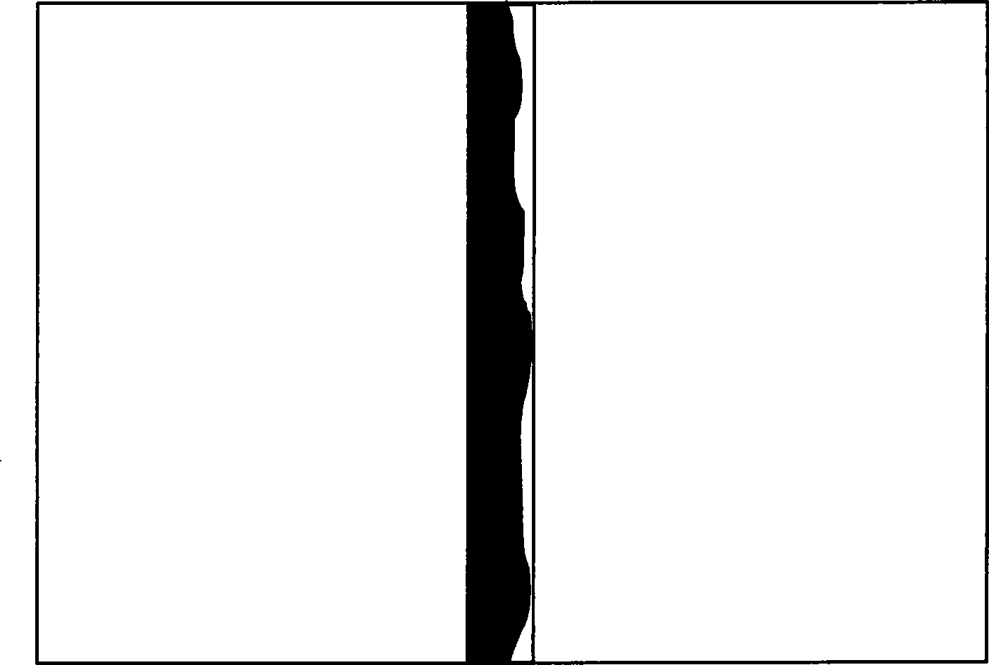
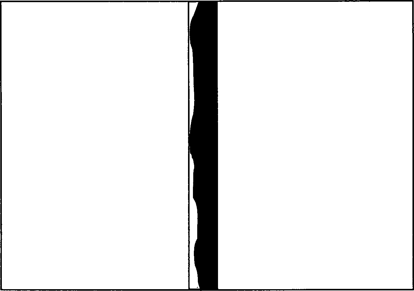
[0032] figure 1 with figure 2 is a schematic diagram of a hypothetical photograph of a neat-edged concrete crack.

[0033] After fixing the probe of the crack width observer, turn on the left light source (usually LED light), illuminate the surface of the detected object with cracks from the left side, and take the first photo. Since the crack side walls of concrete have different components, each component has a different refractive index for light, resulting in reflection results such as figure 1 As shown in , on the crack boundary far away from the light source, each point has a different degree of error;

[0034] Then turn off the light source used for the first photoshoot, and turn on the light source on the other side at the same time, illuminate from the right side, and take the second photoshoot. Similarly, the crack side walls of c...


PUM


Abstract

The invention relates to an accurate crack width measuring method, comprising: positioning a probe of a crack width visualizer; then respectively turning on the light source of one side of the crack width visualizer to illuminate the surface of a measured object with the crack and take photos; processing the taken photos to obtain the clear photos of the crack boundary. The method can obtain the accurate crack boundary, avoid the problem of the inaccurate crack boundary caused by taking photos for one time, greatly improve the accuracy of the crack width detection, and provide reliable guarantee for people to process security detection of concrete, building and equipment.

Description

technical field [0001] The invention relates to a method for detecting cracks in concrete, buildings and equipment, specifically a method for accurately detecting and calculating cracks. Background technique [0002] During the use of concrete, bridges, roads and some equipment, cracks will occur in buildings due to various reasons, especially for bridges, highways, equipment with high safety factor requirements, etc. Cracks may lead to major accidents. The cracks must be observed and monitored regularly, and if the cracks exceed the safe range, they must be dealt with in time. [0003] The commonly used detection instrument is the crack width observer. There are many kinds of crack width observers on the market. The main components of these products basically include light source, microscopic imaging lens, miniature camera and electronic image display screen. The principle of this instrument is: use a light source to illuminate the surface of the detected object containing...

Claims


Application Information

Patent Timeline
Patent Type & Authority Applications(China)
IPC IPC(8): G01B11/02
Inventor 罗兵
Owner 深圳市思韦尔检测科技有限公司
Why Eureka
Try Eureka