Device and method for online monitoring particles on surface of optical elements

A technology of surface particles and optical components, applied in the direction of optical testing flaws/defects, etc., to ensure stable operation

Active Publication Date: 2016-09-07
INST OF AUTOMATION CHINESE ACAD OF SCI
View PDF5 Cites 6 Cited by
  • Summary
  • Abstract
  • Description
  • Claims
  • Application Information

AI Technical Summary

Problems solved by technology

[0004] The main purpose of the embodiments of the present invention is to provide an online monitoring device for particles on the surface of optical components, which at least partly solves the technical problem of how to monitor pollutants on the surface of optical components with different resolutions

Method used


Image

  • Device and method for online monitoring particles on surface of optical elements
  • Device and method for online monitoring particles on surface of optical elements
  • Device and method for online monitoring particles on surface of optical elements

Examples


Embodiment Construction

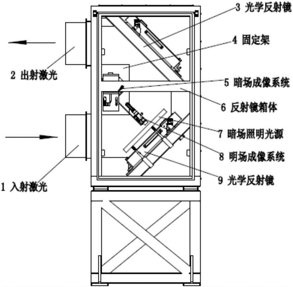
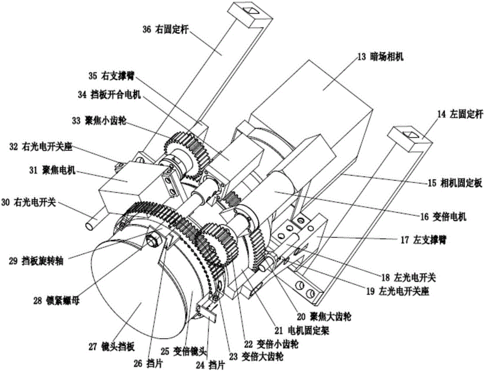
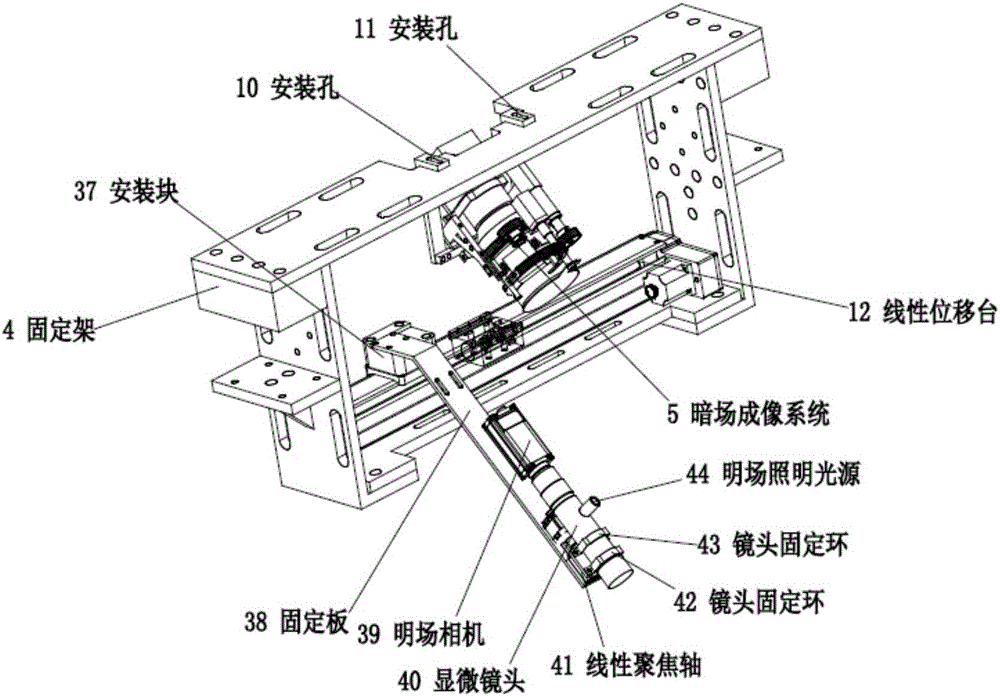
[0025] The technical problems solved by the embodiments of the present invention, the technical solutions adopted and the technical effects achieved are clearly and completely described below in conjunction with the accompanying drawings and specific embodiments. Apparently, the described embodiments are only some of the embodiments of the present application, not all of them. Based on the embodiments in the present application, all other equivalent or obviously modified embodiments obtained by persons of ordinary skill in the art without creative efforts fall within the protection scope of the present invention.

[0026] It should be noted that, in the following description, many specific details are given for the convenience of understanding. It may be evident, however, that the present invention may be practiced without these specific details.

[0027] It should be noted that, in the case of no explicit limitation or conflict, various embodiments of the present invention a...


PUM


Abstract

The invention discloses a device and method for online monitoring particles on the surface of optical elements. The device comprises optical reflectors (3,9), a fixing rack (4), a dark field imaging system (5), an optical reflector case (6), two dark field illumination sources (7), a bright field imaging system (8), and a linear displacement platform (12); wherein two optical reflectors (3,9) and the fixing rack (4) are arranged on the optical reflector case (6); the dark field imaging system (5), the bright field imaging system (8), and the linear displacement platform (12) are arranged on the fixing rack (4), the linear displacement platform (12) drives the bright field imaging system (8) to move; and two dark field illumination sources (7) are arranged on two sides of the optical reflector (9). The provided device and method can monitor the pollutants on the surface of optical elements under different resolutions.

Description

technical field [0001] The embodiments of the present invention relate to the technical field of optical element surface cleanliness monitoring, and in particular to an on-line monitoring device for particles on the surface of an optical element and an on-line monitoring method thereof. Background technique [0002] There are several reflecting mirrors in the high-energy laser operating device, and the operating route of the laser is changed by the reflection of the mirror body. If there is particle contamination on the mirror surface, the high-energy laser will cause damage to the mirror surface. Therefore, in order to ensure the stable operation of the high-energy laser operating device, it is urgent to develop a monitoring system for monitoring the clean state of the mirror. [0003] In view of this, the present invention is proposed. Contents of the invention [0004] The main purpose of the embodiments of the present invention is to provide an online monitoring devi...

Claims


Application Information

Patent Timeline
Patent Type & Authority Applications(China)
IPC IPC(8): G01N21/94
CPCG01N21/94
Inventor 张大朋张正涛丁文东徐德
Owner INST OF AUTOMATION CHINESE ACAD OF SCI
Why Eureka
Try Eureka