Wall drilling machine

A drilling machine and wall technology, which is used in work accessories, manufacturing tools, stone processing equipment, etc., can solve the problems of the accuracy of personnel drilling safely, achieve accurate drilling position and size, facilitate drilling, and enhance stability. sexual effect

Inactive Publication Date: 2018-11-16
ANHUI NORMAL UNIV
View PDF5 Cites 7 Cited by
  • Summary
  • Abstract
  • Description
  • Claims
  • Application Information

AI Technical Summary

Problems solved by technology

Solved the problem of personnel safety and the accuracy of drilling when drilling holes in higher buildings

Method used


Image

  • Wall drilling machine
  • Wall drilling machine
  • Wall drilling machine

Examples


Embodiment Construction

[0022] Below in conjunction with accompanying drawing and embodiment of description, specific embodiment of the present invention is described in further detail:

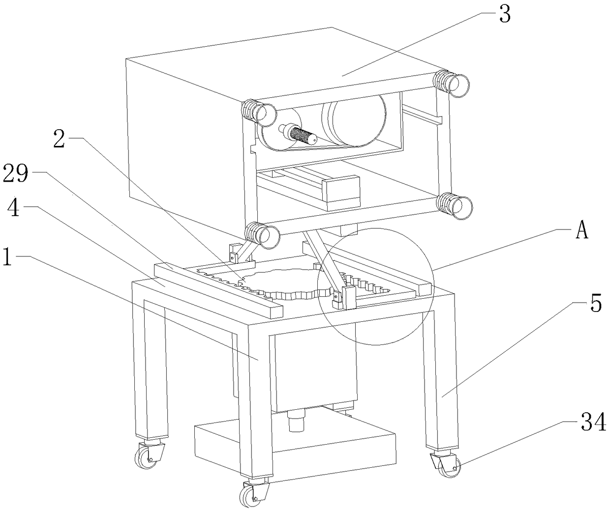
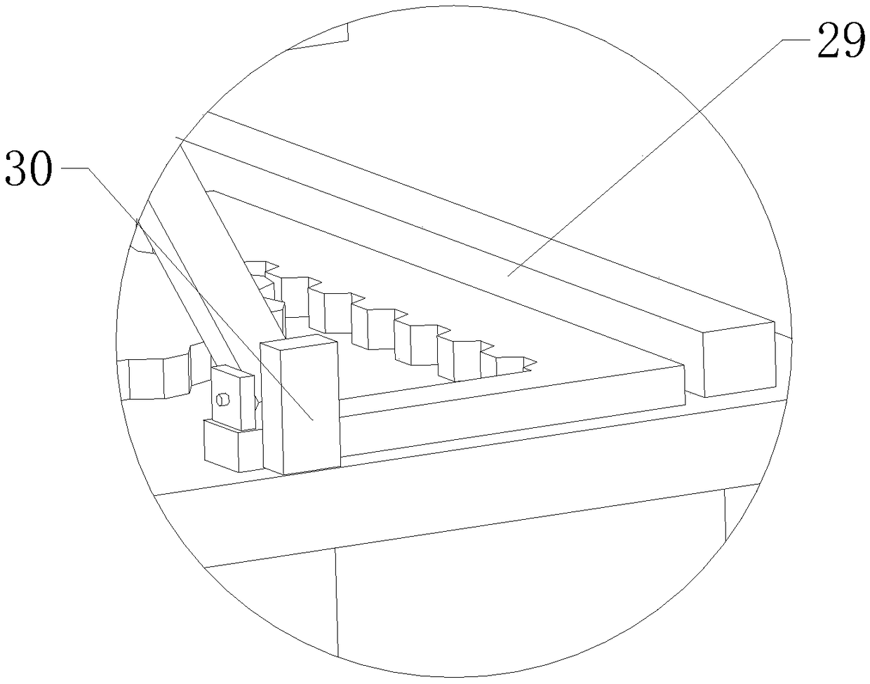
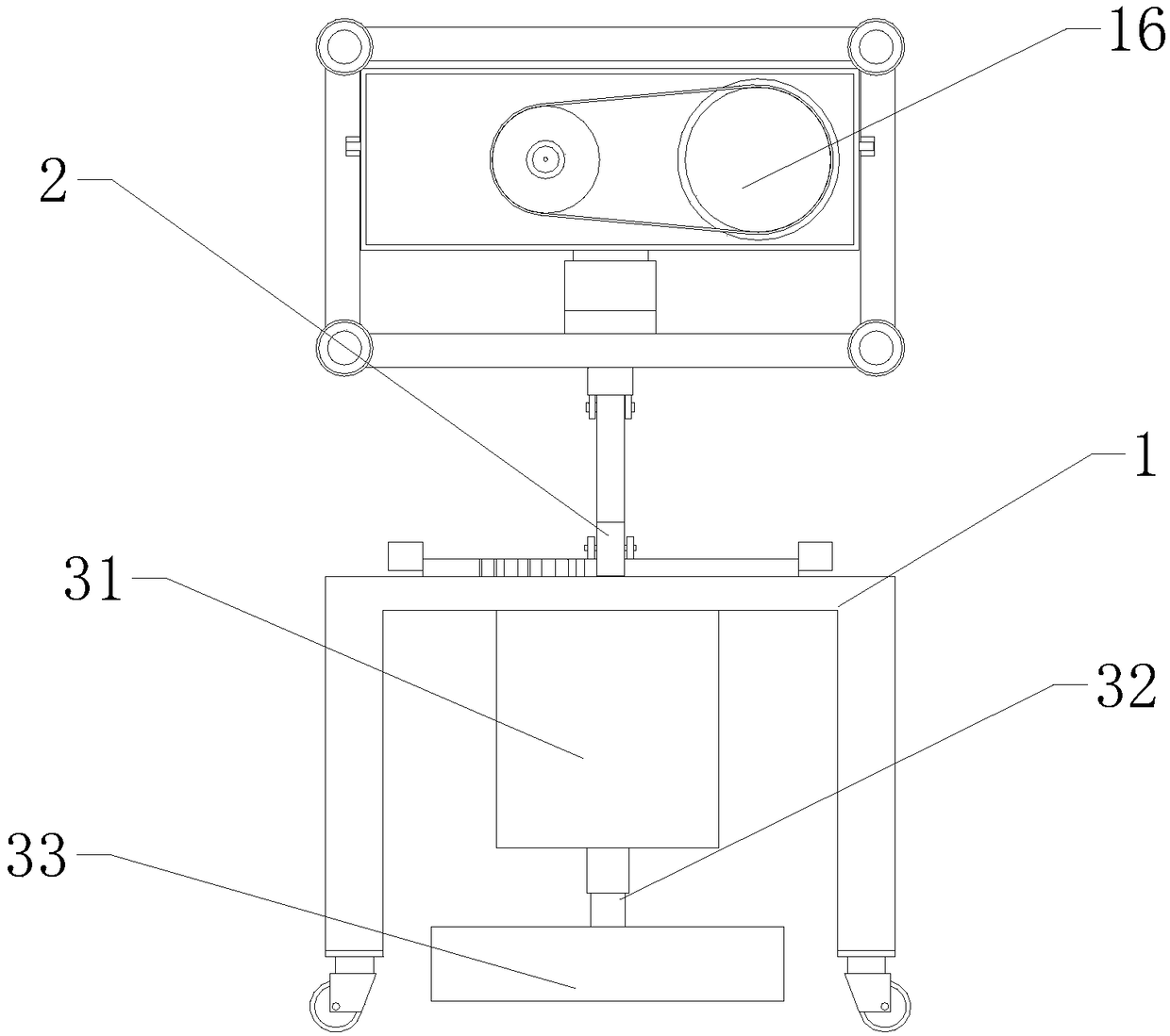
[0023] refer to Figure 1 to Figure 7 A wall drilling machine shown includes a base 1, a lifting mechanism 2 and a punching mechanism 3, the base 1 includes a rectangular workbench 4, and a plurality of support columns 5 are vertically arranged around the workbench 4, The lifting mechanism 2 includes a tightening assembly and a symmetrically arranged lifting rod 11. The tightening assembly includes a rotating motor 6, a gear 7, a first rack 8 and a second rack 9, and the rotating motor 6 is fixedly arranged under the workbench 4. , and the output end of the rotating motor 6 extends through the workbench 4 to the workbench 4, the gear 7 is fixedly connected to the output end of the rotating motor 6, and the first rack 8 and the second rack 9 are respectively arranged on both sides of the gear 7 And the first rack 8 ...


PUM


Abstract

The invention relates to the field of building construction appliances, in particular to a wall drilling machine. The wall drilling machine comprises a base, a lifting mechanism and a perforating mechanism. The lifting mechanism comprises a tightening assembly and symmetrically arranged lifting rods. The tightening assembly comprises a rotating motor, gears, first racks and second racks. The rotating motor is fixedly arranged below the base, the gears are fixedly connected to the output end of the rotating motor, the first racks and the second racks are separately arranged on two sides of thegear and are in engaged connection to the gear, fixed plates vertical to the corresponding first racks or second racks are also arranged at the tail ends of the first rack and the second rack, and thelifting rods are hinged to the corresponding fixed plates. The lifting mechanism is also provided with a supporting rod, and the lifting rods are hinged to the supporting rod. The perforating mechanism comprises a mounting frame and a drilling assembly. The mounting frame is fixedly mounted on the lifting rods, and the drilling assembly is arranged in the mounting frame. The perforating precisionat the high altitude of a wall is improved and the drilling safety problem is solved.

Description

technical field [0001] The invention relates to the field of building construction appliances, in particular to a wall drilling machine. Background technique [0002] After the construction of many buildings is completed at present, some interior decoration, wiring and installation of heating equipment etc. need to be drilled on the wall, and many times also need to be drilled at the height of the wall. The traditional operation method adopts manual operation with scaffolding or ladders, but there are many shortcomings in manual operation. First of all, when personnel work at high places, they need to change various postures due to drilling operations, which may cause personnel to fall from high altitude. It poses a great threat to personnel safety. Secondly, due to the limited physical strength of manual operations at high places, problems such as inaccurate drilling positions and deviations will occur. Therefore need the drilling device of such a kind of wall height, solv...

Claims


Application Information

Patent Timeline
Patent Type & Authority Applications(China)
IPC IPC(8): B28D1/14B28D7/00
CPCB28D1/14B28D7/00
Inventor 吴长义陈浩宋凤楼
Owner ANHUI NORMAL UNIV
Why Eureka
Try Eureka