Mould cavity numerical control machining spiral curve track planning method

A technology of curved trajectory and cavity, which is applied in the field of cavity CNC machining spiral curve trajectory planning, can solve the problems that the cutting process of narrow and long and complex cavity cannot be directly applied, and does not meet the requirements of high-speed machining of complex cavity, so as to achieve continuous tool trajectory, The effect of improving processing efficiency

Inactive Publication Date: 2009-06-10
SHANGHAI JIAO TONG UNIV
View PDF1 Cites 19 Cited by
  • Summary
  • Abstract
  • Description
  • Claims
  • Application Information

AI Technical Summary

Problems solved by technology

Its disadvantages are: the application of this method is still limited to the processing of circular or nearly circular contour cavities, and it cannot be directly applied to the cutting of narrow and long complex cavities with islands, and it does not meet the high-speed processing requirements of complex cavities. Processing requirements

Method used


Image

  • Mould cavity numerical control machining spiral curve track planning method
  • Mould cavity numerical control machining spiral curve track planning method
  • Mould cavity numerical control machining spiral curve track planning method

Examples


Embodiment Construction

[0025] The technical solution of the present invention will be described in further detail below in conjunction with the accompanying drawings and embodiments. The following examples are not intended to limit the present invention.

[0026] The cavity numerical control machining spiral curve track planning method proposed by the present invention is carried out according to the following steps:

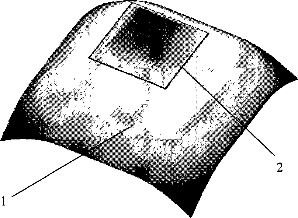
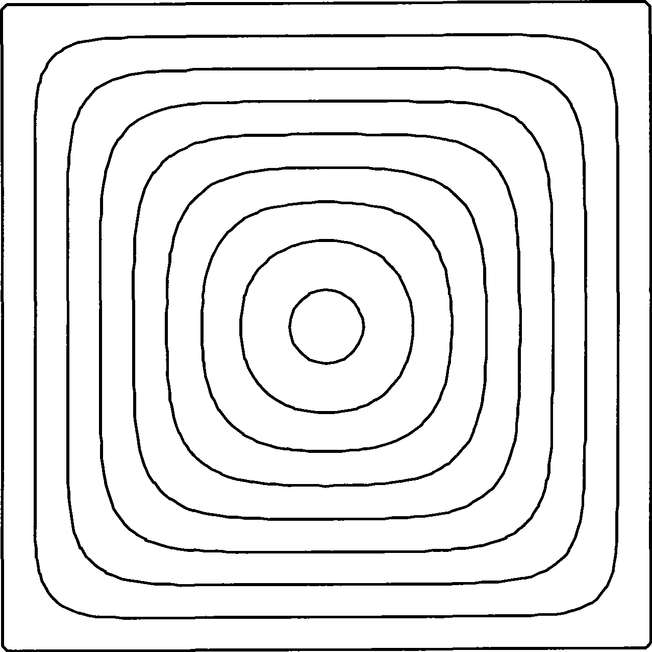
[0027] 1. First, the implicit description of the cavity boundary must be embedded into the level set function of the higher one-dimensional space. The zero level set of the level set function is the cavity boundary, and the level set function is initialized as a signed distance function. Such as figure 1 As shown in the rectangular cavity, embed it into a higher one-dimensional level set function, such as figure 2 As shown, among them, 1 is the level set function, 2 is the zero level set of the level set function, and the zero level set 2 is the rectangular cavity.

[0028] 2. Con...


PUM


Abstract

The invention relates to a method for programming a spiral curve track through die cavity numerical control machining .The boundary of a die cavity is embedded into a level set function of a high one-dimensional space; a zero level set of the level set function is the boundary of the die cavity; and the level set function is initialized to a sign distance function. Bias of the boundary of the die cavity is obtained through the solution of a level set equation; and a speed function of the level set equation is corrected so that a high-curvature region can be smooth in generating a bias line. The distance between the bias lines is controlled through the control of time for boosting the boundary; in the process of boosting the boundary of the die cavity, the complex topological change is naturally treated; and the spiral curve track is programmed in different regions respectively. The method is suitable for programming a cutter track of a numerical control machining system with a common die cavity and a complex die cavity; the cutter track is continuous and smooth; and for the complex die cavity with island, the method can realize automatic division in regions and carry out spiral curve track programming in different regions.

Description

technical field [0001] The invention relates to a method for planning a helical curve trajectory in numerically controlled machining of a cavity, which can be used for high-speed cutting of the cavity and belongs to the field of digital manufacturing. Background technique [0002] In the field of digital manufacturing of the cavity, the tool trajectory directly affects the processing efficiency of the cavity, the quality of the processed surface and the vibration of the processing area. Therefore, how to plan a reasonable and efficient tool path has always been an important research content in the industry and academia. The tool path of the current cavity is mainly in the form of line cutting and ring cutting. The problem with the line-cutting method is: the line-cutting tool path of a complex cavity with multiple islands in the cavity and the boundary and island contours may include free-form curves. It is necessary to frequently enter and exit the tool, or alternate betwe...

Claims


Application Information

Patent Timeline
Patent Type & Authority Applications(China)
IPC IPC(8): G05B19/41
Inventor 丁汉庄春刚熊振华
Owner SHANGHAI JIAO TONG UNIV
Why Eureka
Try Eureka