Automatic reciprocating type sprue removing saw bed and material-handle removing method

A reciprocating and gate-removing technology, which is applied in the direction of sawing machine devices, metal sawing equipment, metal processing equipment, etc., can solve the problems of inability to perform automatic reciprocating work, unsuitable for popularization and use, and slow work efficiency, so as to prevent removal Safety and stability, convenient division of work, and the effect of improving efficiency

Inactive Publication Date: 2015-11-25
菲斯达精密工业部件(苏州)有限公司
View PDF6 Cites 3 Cited by
  • Summary
  • Abstract
  • Description
  • Claims
  • Application Information

AI Technical Summary

Problems solved by technology

[0002] The product coming out of the die-casting mold has a runner and a handle, and it is often a trimming mold through the removal process. However, for the vertical multi-position pouring method, the trimming mold cannot meet this requirement. This feeding method may The removal of runners and handles is realized by automatic reciprocating degating sawing machines. However, the general degating sawing machines on the market can only cut once in a single channel, and cannot perform automatic reciprocating work. The work efficiency is slow and the cutting speed is slow. , not suitable for promotional use

Method used


Image

  • Automatic reciprocating type sprue removing saw bed and material-handle removing method
  • Automatic reciprocating type sprue removing saw bed and material-handle removing method
  • Automatic reciprocating type sprue removing saw bed and material-handle removing method

Examples


Embodiment Construction

[0020] The following will clearly and completely describe the technical solutions in the embodiments of the present invention with reference to the accompanying drawings in the embodiments of the present invention. Obviously, the described embodiments are only some, not all, embodiments of the present invention. Based on the embodiments of the present invention, all other embodiments obtained by persons of ordinary skill in the art without making creative efforts belong to the protection scope of the present invention.

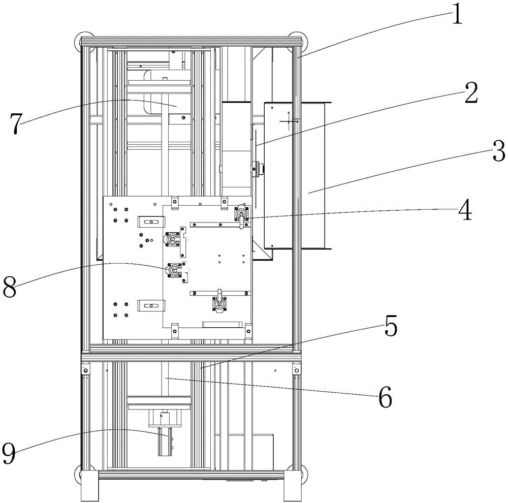
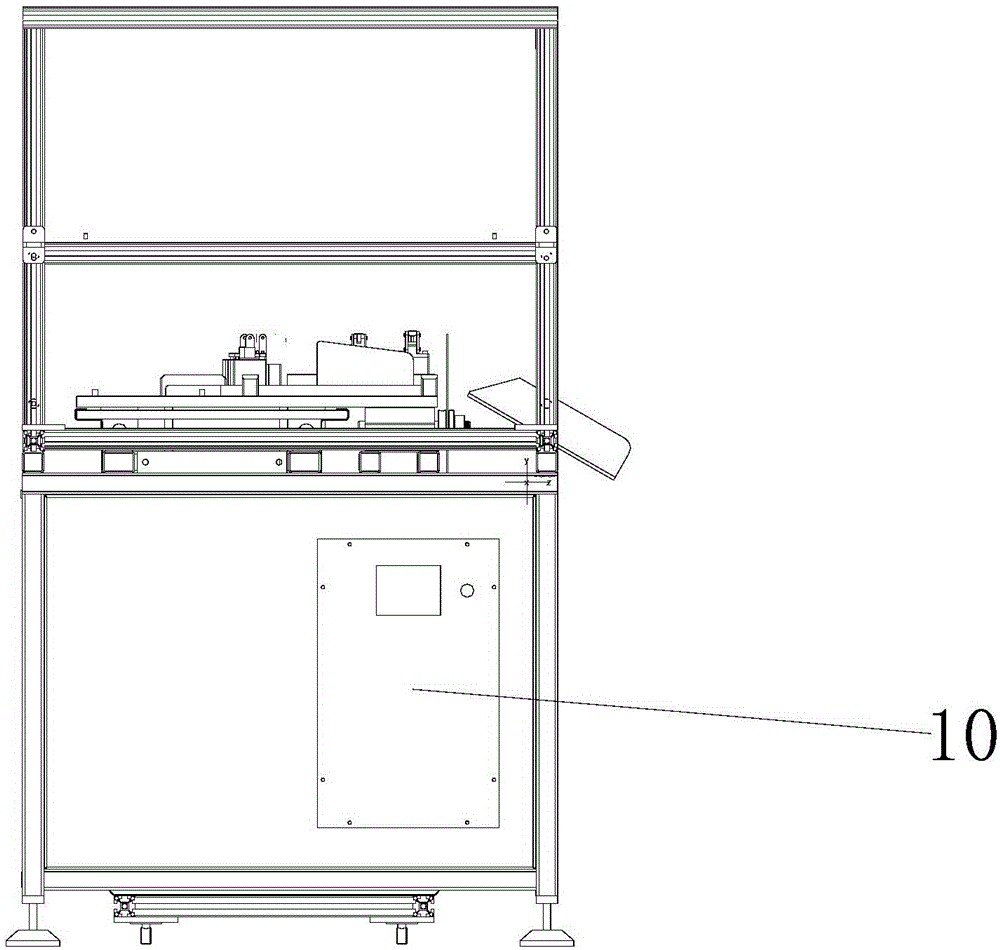
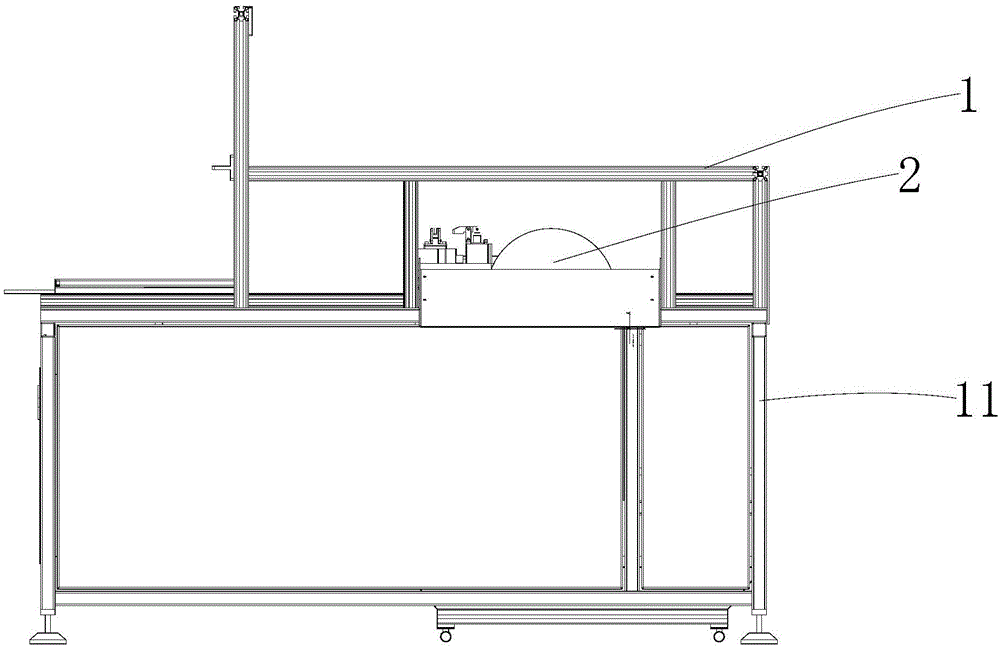
[0021] see Figure 1-4 , the present invention provides a technical solution: an automatic reciprocating degating sawing machine, including a frame 1, a saw blade 2, a blanking slide 3, a clamping cylinder 4, a clamp sliding guide 5, a screw rod 6, and a saw blade motor 7. Saw machine clamping fixture 8, servo motor 9, electrical control box 10 and box legs 11, saw blade motor 7 is installed in the inner cavity of frame 1, and the rotor shaft of saw blade moto...


PUM


Abstract

The invention discloses an automatic reciprocating type sprue removing saw bed and a material-handle removing method. The sprue removing saw bed comprises a machine frame, a saw web, a discharge sliding plate, clamping steam cylinders, clamp sliding guide rails, a lead screw, a saw-web motor, saw bed clamping fixtures, a servo motor, an appliance control cabinet and cabinet legs, wherein the saw-web motor is mounted in the inner cavity of the machine frame; the rotor shaft of the saw-web motor is connected with the saw web; the discharge sliding plate is arranged on the right side of the machine frame; the saw bed clamping fixtures are arranged in the inner cavity of the machine frame; each clamping steam cylinder is mounted at the top of the corresponding saw bed clamping fixture; the clamp sliding guide rails are arranged in the inner cavity of the machine frame; the lead screw is mounted in the inner cavity of the machine frame; the servo motor is connected to the top of the lead screw; the appliance control cabinet is arranged at the back of the machine frame. The automatic reciprocating type sprue removing saw bed controls the residual height after an inner sprue is removed, so that the removing efficiency of the inner sprue is improved; products can be prevented from being damaged by sawing; the removing safety and the removing stability are guaranteed; therefore, the sprue removing saw bed is suitable for popularization and usage.

Description

technical field [0001] The invention relates to the technical field of removing a vertical feeding shank of a heat sink of a die-casting part, in particular to an automatic reciprocating degating sawing machine and a method for removing a material shank. Background technique [0002] The product coming out of the die-casting mold has a runner and a handle, and it is often a trimming mold through the removal process. However, for the vertical multi-position pouring method, the trimming mold cannot meet this requirement. This feeding method may The removal of runners and material handles is achieved through automatic reciprocating degating sawing machines. However, the general degating sawing machines on the market can only cut once in a single channel, and cannot perform automatic reciprocating work. The work efficiency is slow and the cutting speed is slow. , not suitable for promotional use. Contents of the invention [0003] The object of the present invention is to pro...

Claims


Application Information

Patent Timeline
Patent Type & Authority Applications(China)
IPC IPC(8): B23D47/00B23D47/04
CPCB23D47/00B23D47/04
Inventor 杨振武
Owner 菲斯达精密工业部件(苏州)有限公司
Why Eureka
Try Eureka