Method for enhancing ultrasonograph quality

An ultrasound image and ultrasound imaging system technology, applied in image enhancement, image data processing, instruments, etc., can solve problems such as loss of dynamic characteristics, inability to truly improve ultrasound image quality, and blurred tissue structure.

Inactive Publication Date: 2009-06-10
SHENZHEN EMPEROR ELECTRONICS TECH
View PDF4 Cites 25 Cited by
  • Summary
  • Abstract
  • Description
  • Claims
  • Application Information

AI Technical Summary

Problems solved by technology

[0005] Although the above commonly used methods suppress noise or enhance the characteristics of tissue structure, while suppressing speckle noise, they blur the tissue structure or l

Method used


Image

  • Method for enhancing ultrasonograph quality
  • Method for enhancing ultrasonograph quality
  • Method for enhancing ultrasonograph quality

Examples


Embodiment Construction

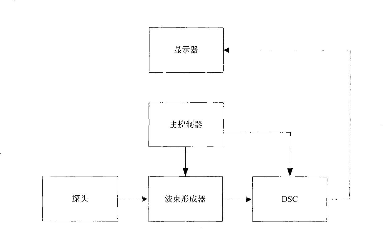
[0037] figure 1 is a typical ultrasound imaging system diagram. In the figure, it consists of a main controller, a probe, a beamformer, a digital scan conversion (DSC, Digital Scan Conversion), and a display. Under the control of the main controller, the probe emits ultrasonic waves, which are received and reflected back from the tissue after a certain delay. of ultrasound. The beamformer performs focus delay, weighting, and summation on the reflected echo signals of each channel to form one or more scanning lines, and then obtains the envelope signal of the scanning echo through filtering, wave detection and other processing. The echo envelope is sent to the digital scan transformation module to complete the coordinate transformation and form image data. The formed image data is then sent to the display module, superimposed with characters, and then output to the display for display.

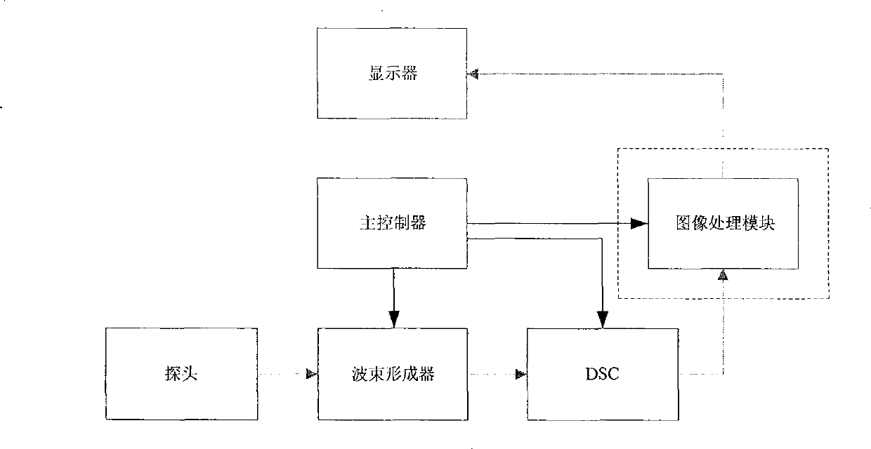
[0038] figure 2 It is the image processing module diagram of the present invention in ...


PUM


Abstract

The invention provides a method for improving the quality of ultrasonic images, which is used for the optimization of display data of ultrasonic scan images in an ultrasonic imaging system. The method comprises the following step of decomposing ultrasonic image date into a plurality of layers by using a Gaussian-Laplacian pyramid decomposition method, carrying out anisotropic diffusion, filtering processing to Gaussian layer data of the decomposition result, carrying out reverse reconstruction to the processed ultrasonic image data, and improving the quality of the ultrasonic images through a plurality of times of iterative processing, wherein a anisotropic diffusion and filtering algorithm is used to calculate diffusion factors in different directions according to the local structural information of the ultrasonic images so as to filter the image data. As a result of the method, information in organizational-structure regions is enhanced and the noises in non-organizational-structure regions are suppressed effectively.

Description

technical field [0001] The invention relates to the technical field of ultrasonic imaging, in particular to digital image processing technology in the ultrasonic imaging technology and a method for improving the quality of ultrasonic images. Background technique [0002] A typical ultrasound imaging system such as figure 1 As shown, it includes an ultrasonic imaging device, and the main controller controls the normal operation of the whole system. Under the control of the main controller, the probe emits ultrasonic waves and receives the ultrasonic waves reflected from the tissue after a certain time delay. The beamformer performs focus delay, weighting, and summation on the reflected echo signals of each channel to form one or more scanning lines, and then obtains the envelope signal of the scanning echo through filtering, wave detection and other processing. The echo envelope is sent to the digital scan transformation module to complete the coordinate transformation and ...

Claims


Application Information

Patent Timeline
IPC IPC(8): G06T5/00
Inventor 刘林泉周传涛
Owner SHENZHEN EMPEROR ELECTRONICS TECH
Why Eureka
Try Eureka