Electric connection device of outdoor high-voltage isolating switch
A technology of high-voltage isolation switch and electrical connection device, applied in the direction of connection, air switch parts, circuits, etc., can solve the problems of affecting the performance stability of the device, reducing the service life, increasing assembly work, etc., to increase dust resistance and corrosion resistance. performance, less conductive connection links, and the effect of ensuring reliability
- Summary
- Abstract
- Description
- Claims
- Application Information
AI Technical Summary
Problems solved by technology
Method used
Image
Examples
Embodiment 1
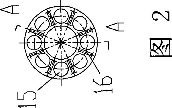
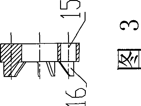
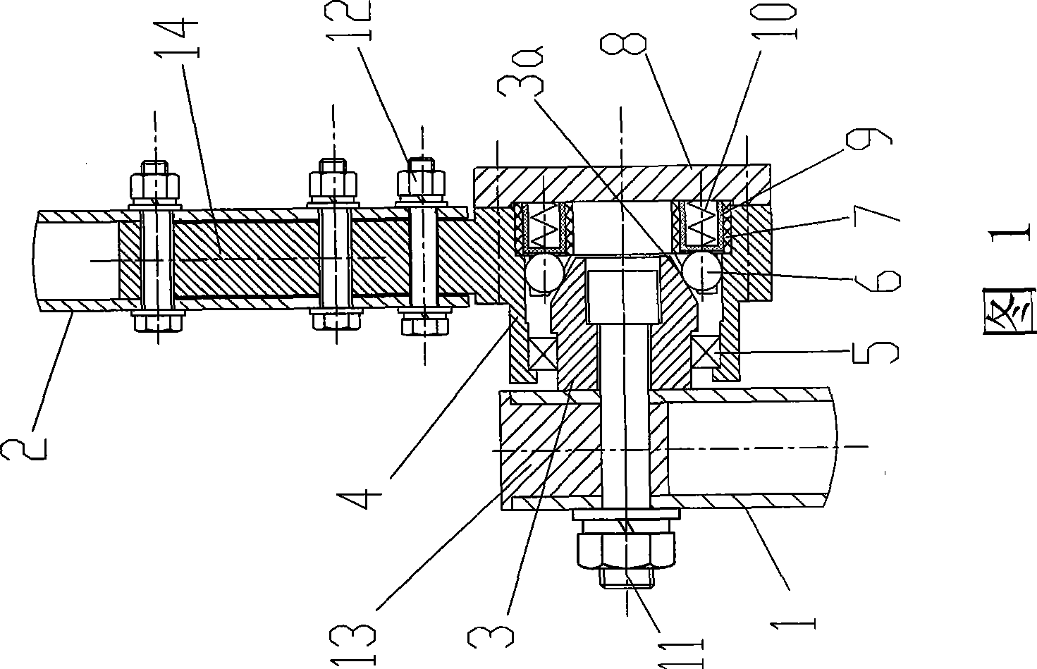
[0021] Embodiment 1: The electrical connection device between the conductive tube and the conductive tube of this high-voltage isolating switch, including the lower conductive tube 1 and the upper conductive tube 2, the lower conductive tube 1 is provided with a support block 13, the lower conductive tube 1 and the support block 13 The bolt 11 is fixedly connected with the shaft seat 3. The shaft sleeve 4 is located outside the shaft seat 3. An insulating bracket 7 for fixing the ball contact finger 6 is arranged inside the shaft sleeve 4. One end of the insulating bracket 7 is cylindrical. There is a boss-shaped partition 16 on one end of the shape, and eight through holes 15 are arranged at the cylindrical part of one end of the insulating support 7, and an insulating bushing 9 and a finger spring 10 are arranged in each through hole 15, and there is a For their corresponding ball contact fingers 6, there are also eight partitions 16 in the shape of bosses on the insulating s...
Embodiment 2
[0027] In this embodiment, the lower conductive pipe 1 is fixedly connected to the shaft seat 3 through bolts 11 , and the end cover 8 is fixedly connected to the shaft sleeve 4 through screws. One end 4a of the inner wall of the shaft sleeve 4 is an inner conical surface, the outer wall of the shaft seat 3 is a cylindrical surface, the ball contact finger 6 is located between the outer wall of the inner conical surface 4a of the shaft sleeve 4 and the outer cylindrical surface of the shaft seat 3, and They are in contact; there are six through holes 15 corresponding to the ball contact fingers 6 at the cylindrical part of one end of the insulating support 7, and the partition 16 on the insulating support 7 is a triangular boss; the bearing 5 used is a sealed The deep groove ball bearing of ring; There is annular groove on the cylindrical outer wall of conductor 14, and other structure and connection relation are identical with embodiment 1.
Embodiment 3
[0028] In the third embodiment, a sealing ring 17 is provided between the contact surface of the end cover 8 and the shaft sleeve 4, and the other is the same as that of the second embodiment.
[0029] There are at least three through holes 15 on the insulating support 7 in the present invention, and its quantity can be selected according to needs, and the number of used ball contact fingers 6 should be the same as the through holes 15 on the insulating support 7.
[0030] The shape of the insulating bracket 7 in the present invention can also adopt other shapes suitable for the shape of the shaft seat 3 and the end cover 8 .
[0031] The lower conductive pipe 1 can also be fixedly connected with the shaft seat 3 through pins.
[0032] Working principle of the present invention is:
[0033] When the lower conductive tube 1 drives the shaft seat 3 to rotate back and forth through the bolt 11, the bearing 5 and the ball contact finger 6 will roll on the outer surface of the sha...
PUM
 Abstract
Description
Claims
Application Information
 - R&D
- Intellectual Property
- Life Sciences
- Materials
- Tech Scout
- Unparalleled Data Quality
- Higher Quality Content
- 60% Fewer Hallucinations
Browse by: Latest US Patents, China's latest patents, Technical Efficacy Thesaurus, Application Domain, Technology Topic, Popular Technical Reports.
© 2025 PatSnap. All rights reserved.Legal|Privacy policy|Modern Slavery Act Transparency Statement|Sitemap|About US| Contact US: help@patsnap.com


