
Method for increasing common mode feedback stability by grounding capacitor

A capacitor and compensation capacitor technology, applied in the direction of negative feedback circuit layout, DC coupled DC amplifier, differential amplifier, etc., can solve the problem of reducing the gain of the common mode feedback amplifier 130

Inactive Publication Date: 2009-06-10
REALTEK SEMICON CORP
View PDF0 Cites 8 Cited by
  • Summary
  • Abstract
  • Description
  • Claims
  • Application Information

AI Technical Summary

Problems solved by technology

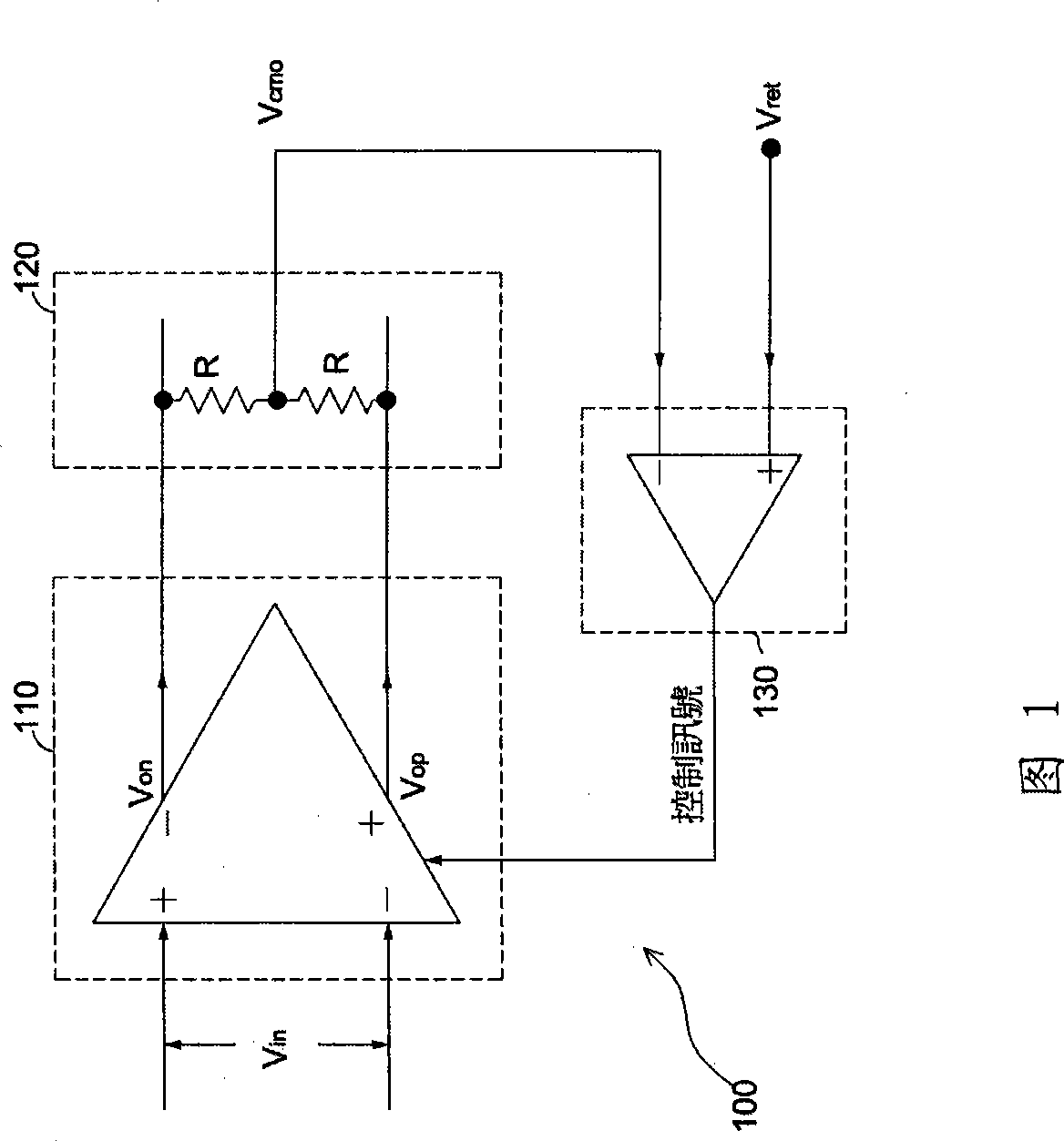
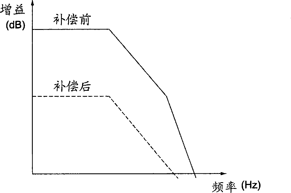
[0003] Since the fully differential operational amplifier 100 with common-mode feedback circuit must be properly compensated, otherwise, when the common-mode output voltage V cmo After being added to the noise, it is easy to cause the common mode output voltage V cmo Oscillation (oscillate) phenomenon occurs, two common compensation methods for common-mode feedback circuits are introduced below. The first compensation method is to use source-level degeneration (source degeneration), through the two inputs of the common-mode feedback amplifier 130 The two transistors at the end, add a resistance, increase its stability by reducing the gain of the common mode feedback amplifier 130, the second compensation method is to reduce the current amount of the control current of the fully differential operational amplifier 110 to the original 1 / N times (N is a positive integer, N>>1), to increase the stability of the overall circuit, please refer to figure 2 , figure 2 In order to use the common mode feedback circuit of these two compensation methods, the frequency response of the amplifier before compensation and after compensation is compared. It can be seen from the figure that these two compensation methods will make the frequency response after compensation sacrifice gain in exchange for the overall circuit. stability

Method used


Image

  • Method for increasing common mode feedback stability by grounding capacitor
  • Method for increasing common mode feedback stability by grounding capacitor
  • Method for increasing common mode feedback stability by grounding capacitor

Examples


Embodiment Construction

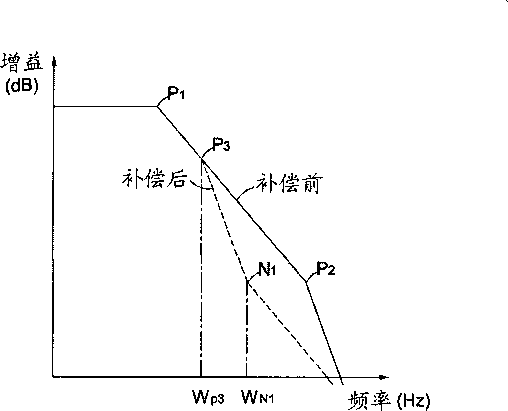
[0026] image 3 It shows the comparison diagram of the frequency response before compensation and after compensation of the common mode feedback circuit of the present invention. The frequency response curve before compensation originally has two poles P 1 ,P 2 , if the gain value of the frequency response of the common mode feedback circuit remains unchanged, it can be added by adding a pole P 3 with a zero point N 1 to improve the phase margin and increase the stability of the circuit, such as image 3 The frequency response curve after medium compensation has two poles P 1 ,P 3 with a zero point N 1 , while the pole P before compensation 2 has been moved to higher frequencies. Therefore, the present invention utilizes an additional compensation circuit to achieve the pole P 3 with zero point N 1 The purpose of implementing the compensation circuit is a combination of capacitors and resistors, such as the following five embodiments.

[0027] Please refer to Figur...


PUM


Abstract

The invention provides a common mode feedback circuit. An amplifier provided with the common mode feedback circuit is compensated by adding a compensating unit so that the frequency response of the amplifier is provided with two poles and a zero point, does not sacrifice a gain value of the amplifier, improves the phase margin, and improves the stability of the circuit.

Description

technical field [0001] The present invention relates to an amplifier, in particular to an amplifier with a common-mode feedback (common-mode feedback) circuit. Background technique [0002] In general, a fully differential operational amplifier (fully differential operation amplifier) ​​with a feedback circuit, the feedback circuit can only determine the differential output voltage (differential output voltage) of the fully differential operational amplifier, but cannot affect its common-mode output voltage. Therefore, the fully differential operational amplifier needs an additional circuit to control the common-mode output voltage, so that the common-mode output voltage Vcmo approaches a reference voltage value (usually the middle value of the two operating voltages), please refer to Figure 1, Figure 1 is a fully differential operational amplifier 100 with a common-mode feedback circuit, which includes a fully differential operational amplifier 110 , a common-mode detector ...

Claims


Application Information

Patent Timeline
IPC IPC(8): H03F3/45H03F1/34
Inventor 李朝政冯介民
Owner REALTEK SEMICON CORP
Learn More