Beam forming method, system and apparatus

A beamforming and beam technology, applied in the field of communications, can solve the problems of high terminal receiving complexity and inapplicability to FDD systems, and achieve the effects of low requirements, reduced computational complexity, and low complexity

Inactive Publication Date: 2009-06-10
HUAWEI TECH CO LTD
View PDF0 Cites 31 Cited by
  • Summary
  • Abstract
  • Description
  • Claims
  • Application Information

AI Technical Summary

Problems solved by technology

[0020] Embodiments of the present invention provide a beamforming method, system and device to solve the problem tha...

Method used


Image

  • Beam forming method, system and apparatus
  • Beam forming method, system and apparatus
  • Beam forming method, system and apparatus

Examples


Embodiment Construction

[0030] The embodiment of the present invention provides a beamforming method, which mainly solves the problem of downlink beamforming. Using downlink detection can overcome the problem of inaccurate uplink detection in the FDD system or the high complexity of the common pilot method. In the embodiment of the present invention, beamforming is performed on each pilot or code sequence with very good correlation, and the pilot or code sequence with very good correlation corresponds to the beam one by one, and the number of pilots is equal to the number of beams. , so the terminal is equivalent to receiving single-antenna data, making terminal detection easier.

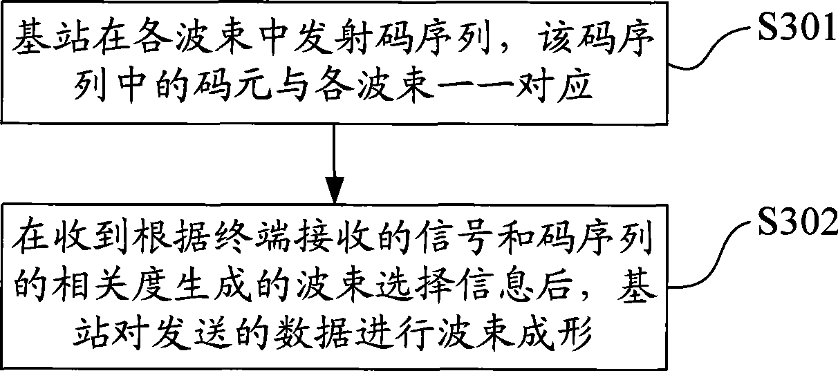
[0031] Such as image 3 As shown, it is a flow chart of the beamforming method of the embodiment of the present invention, which specifically includes the following steps:

[0032] In step S301, the base station transmits a code sequence in each beam, and symbols in the code sequence correspond to each beam one by one. T...


PUM


Abstract

The embodiment of the invention discloses a beam shaping method. The method comprises the following steps: a base station emits a code sequence in each beam, and a code element of the code sequence corresponds to each beam one by one; after beam selection information generated according to a signal received by a terminal and degree of association of the code sequence is received, the base station carries out beam shaping on data to be transmitted. Through the embodiment, the terminal generates the beam shaping information through calculation of degree of association and feeds the information back the base station; the base station carries out beam shaping on the data to be transmitted according to the beam selection information;and the method has small increase of the terminal calculation and unhigh requirement on terminal complexity, not only greatly reduces the burden of he base station, but also greatly avoids possibility of failure of beam shaping and improves the performance of an intelligent antenna system.

Description

technical field [0001] The present invention relates to the technical field of communications, and in particular to a beamforming method, system and device. Background technique [0002] The base station smart antenna is an array antenna composed of multiple antenna units. By adjusting the weighted amplitude and phase of each unit signal and changing the pattern of the array, interference can be suppressed and the signal-to-noise ratio can be improved. The smart antenna of the base station can automatically measure the direction of the user, and point the beam to the user, so that the beam follows the user. figure 1 It is the simplest structure of the smart antenna - the linear array structure. In the linear array structure, the array elements are generally set to be equally spaced, such as figure 1 The spacing between adjacent array elements is shown as d. [0003] In smart antenna applications, it is generally assumed that the incident wave is a far-field source, that is...

Claims


Application Information

Patent Timeline
IPC IPC(8): H04B7/04H04L1/06
CPCH04B7/0695H04B7/0619H04B7/0617
Inventor 曾云宝李亚娟鲁艳玲
Owner HUAWEI TECH CO LTD
Why Eureka
Try Eureka