

Layered type balloon transformer
A technology of balancing transformers and transformers, which is applied in the directions of broadband transformers, transformer/inductor components, transformer/inductor coils/windings/connections, etc., which can solve the problems of lack of universality and inapplicability of transformers
- Summary
- Abstract
- Description
- Claims
- Application Information
AI Technical Summary
Problems solved by technology
Method used
Image

Examples
Embodiment 1
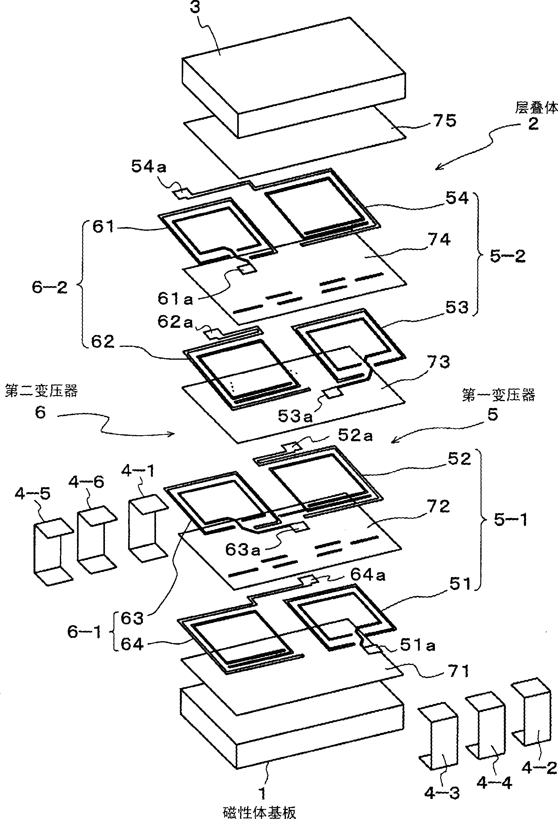
[0044] figure 1 It is an exploded perspective view of the laminated balanced-unbalanced transformer of the first embodiment of the present invention; figure 2 This is an appearance diagram of a laminated balun transformer.
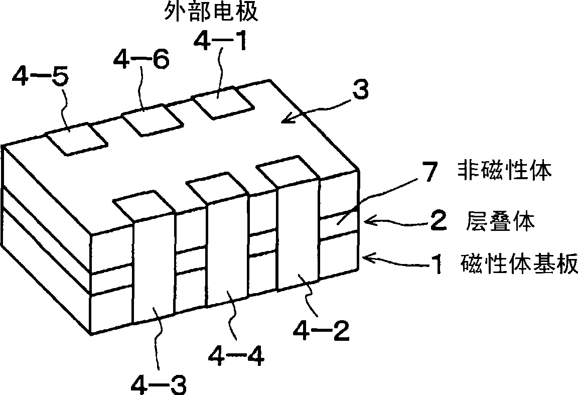
[0045] Such as figure 2 As shown, in this embodiment, the laminated balun transformer is composed of: a magnetic substrate 1 as the first magnetic substrate; a laminated body 2 laminated on the magnetic substrate 1; The magnetic substrate 3 on the second magnetic substrate; and the external electrodes 4-1 to 4-6.
[0046] Laminate 2 as figure 1 As shown, there are: a first transformer 5; a second transformer 6 with substantially the same structure and in the same direction as the first transformer 5; and an insulator 7 ( figure 2 reference).
[0047] The insulator 7 is, for example, a dielectric, and is formed by laminating insulator layers 71 to 75 . Further, the first and second transformers 5 and 6 are patterned on such insulator layers 71 to...
Embodiment 2
[0080] Next, a second embodiment of the present invention will be described.
[0081] Figure 13 It is an exploded perspective view of a laminated balanced-unbalanced transformer according to the second embodiment of the present invention; Figure 14 It is a top view showing the conductor pattern of the lower layer of the primary side winding 8-1; Figure 15 is a top view showing the middle insulator layer 72; Figure 16 It is a top view showing the conductor pattern on the upper layer of the primary side winding 8-1; Figure 17 is a top view showing the conductor pattern of the lower layer of the secondary side winding 8-2; Figure 18 is a top view showing the middle insulator layer 74; Figure 19 It is a top view showing the conductor pattern of the upper layer of the secondary winding 8-2.
[0082] Such as Figure 13 As shown, the laminated balun of this embodiment has a structure in which a laminated body 2 including a transformer 8 is sandwiched between magnetic sub...
Embodiment 3
[0096] Next, a third embodiment of the present invention will be described.
[0097] Figure 21 It is an equivalent circuit diagram of a laminated balun transformer according to a third embodiment of the present invention.
[0098] The example, as figure 1 The stacked-type balun transformer shown has a structure in which a stacked body 2 is sandwiched between magnetic substrates 1 and 3, and external electrodes 4-1 to 4-6 are mounted on its side surfaces, as shown in Figure 21 As shown, n (n=an integer equal to or greater than 3) pieces of first transformer 9 ( 1 ) to nth transformer 9 (n) are included in laminated body 2 .
[0099] Specifically, the left end of the primary side winding 9-1 of the first transformer 9(1) is connected to the external electrode 4-1, which is an unbalanced terminal; and the right end is connected to the external electrode 4-2, which is a first balanced terminal. In addition, in the last-stage nth transformer 9 (n), the left end of the seconda...
PUM
| Property | Measurement | Unit |
|---|---|---|
| impedance | aaaaa | aaaaa |
| impedance | aaaaa | aaaaa |
Abstract
Description
Claims
Application Information