Method of controlling adjusting hole

A control method and a technology of adjusting holes, which are applied in flow control, flow control of auxiliary non-electric power, control/regulation systems, etc., and can solve problems such as wear, control characteristic changes, and inability to achieve control.

Inactive Publication Date: 2011-04-06
RESONAC HOLDINGS CORPORATION +1
View PDF3 Cites 0 Cited by
  • Summary
  • Abstract
  • Description
  • Claims
  • Application Information

AI Technical Summary

Problems solved by technology

[0004] However, there is a problem with this method that wear occurs due to mechanical sliding, and as a result, control characteristics change over time, and control becomes impossible.

Method used


Image

  • Method of controlling adjusting hole
  • Method of controlling adjusting hole
  • Method of controlling adjusting hole

Examples


Embodiment

[0142] Whether the control device for the regulating hole of the present invention can regulate the fluid flow has been tested, and an embodiment of the experiment (experimental example) will be described below. However, the present invention is not limited by this Example.

[0143]

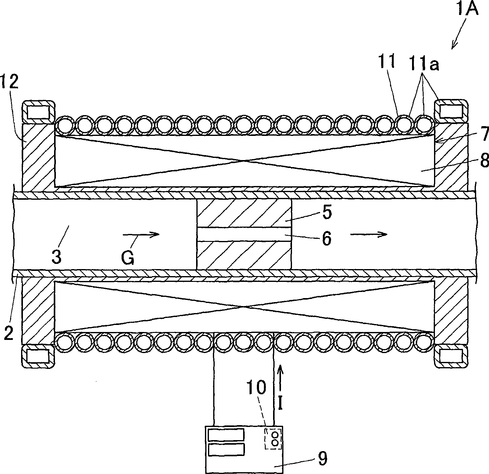
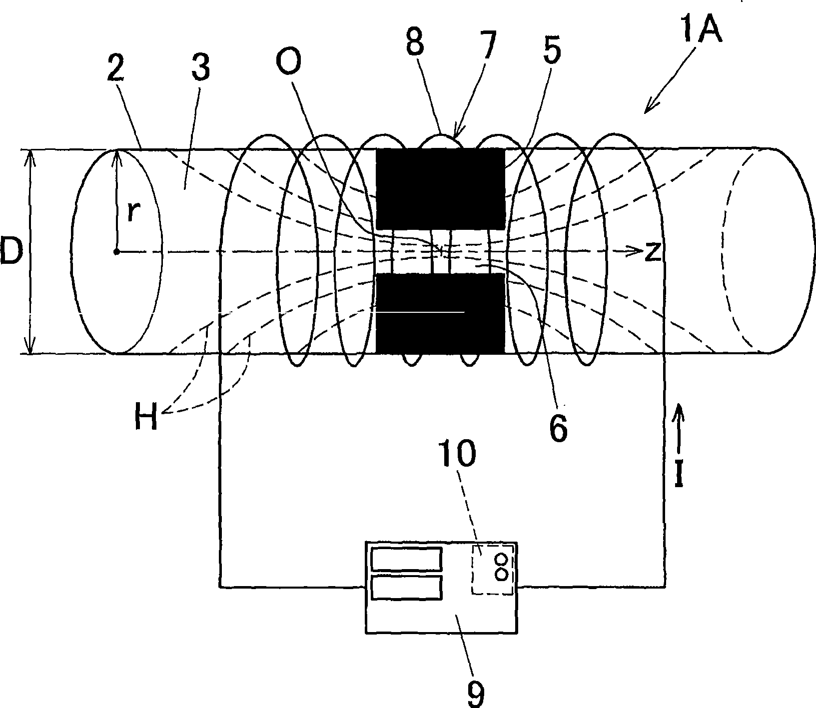
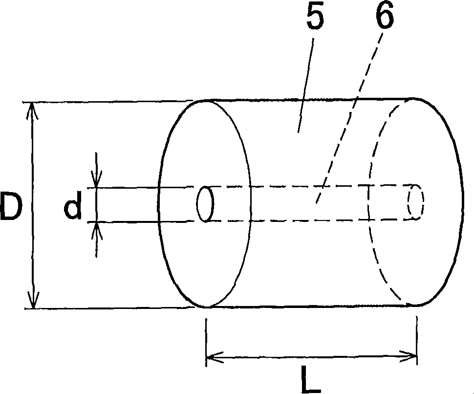
[0144] Fig. 7 is a schematic diagram of a control device (1C) for an adjustment hole used in this example (experimental example). In the control device (1C), the diameter D of the pipeline (3) of the pipe body (2) (see figure 2 ) is 12mm. The tube body (2) is made of transparent acrylic, and its wall thickness is 1-2mm. The length L of the partition wall (5) is 12 mm. Such as image 3 As shown, in the central portion of the partition (5), an adjustment hole (6) is provided straight through along the axial direction of the pipeline (3), and the diameter d of the adjustment hole (6) is 1.0mm.

[0145] In this control device (1C), (51) is an electric motor, (52) is a speed controller, (53) i...


PUM


Abstract

A method of controlling a regulating hole for regulating an amount of light, a flow rate of fluid, a pressure of fluid passing through a tubular passage is provided. A partition wall 5 formed by a viscoelastic solid containing magnetic particles is transversely disposed in the tubular passage 3 through which light or fluid passes. The partition wall 5 is provided with a regulating hole 6 for regulating an amount of the light, a flow rate of the fluid, or a pressure of the fluid so that the regulating hole 6 penetrates in an axial direction. Magnetic field gradient is generated the partition wall 5 in a radial direction in the tubular passage 3 to thereby change an opening degree of the regulating hole 6.

Description

[0001] This application claims priority based on Japanese Patent Application Japanese Patent Application No. 2006-111598 filed on April 14, 2006, and the disclosed content constitutes a part of this application. technical field [0002] The present invention relates to a method for controlling a regulating hole for regulating the amount of light passing through a pipeline, the flow rate of a fluid or the pressure of a fluid, and a control device for regulating the hole. Background technique [0003] In the past, the method of controlling the flow rate of the fluid passing through the pipeline was mainly a mechanical control method such as control with a needle valve. [0004] However, this method has a problem in that wear occurs due to mechanical sliding, and as a result, the control characteristics change with the passage of time to the extent that control cannot be achieved. [0005] In addition, it has been proposed to use a magnetic fluid containing magnetic particles i...

Claims


Application Information

Patent Timeline
Patent Type & Authority Patents(China)
IPC IPC(8): H01L41/12H01L41/20G03B9/02
CPCF16K31/06G03B9/02G05D7/0186G05D7/005G02B26/02F16K13/10H01L41/12Y10T29/49Y10T137/0318H10N35/00
Inventor 山口博司榎本正敏
Owner RESONAC HOLDINGS CORPORATION
Why Eureka
Try Eureka