Two stage oil-gas separator

A technology of oil and gas separator and main separator, which is applied in the direction of machine/engine, engine components, engine lubrication, etc., can solve the problems of high manufacturing cost, poor combustion, large space occupied, etc., so as to save the layout space, oil and gas, etc. Completely separated, cleverly arranged effects

Inactive Publication Date: 2009-06-17
CHERY AUTOMOBILE CO LTD
View PDF0 Cites 16 Cited by
  • Summary
  • Abstract
  • Description
  • Claims
  • Application Information

AI Technical Summary

Problems solved by technology

The labyrinth oil and gas separation integrated in the cover is not efficient, and takes up a lot of space, and the manufacturing cost is high
The condensing oil-gas separator has a short separation path for the oil-gas mixture, and some of the mixture is still discharged into the atmosphere, causing air pollution, or entering the intake pipe for combustion, resulting in serious consequences such as poor combustion and carbon deposits on the valve.

Method used


Image

  • Two stage oil-gas separator
  • Two stage oil-gas separator
  • Two stage oil-gas separator

Examples


Embodiment Construction

[0018] The present invention will be specifically described below in conjunction with the accompanying drawings.

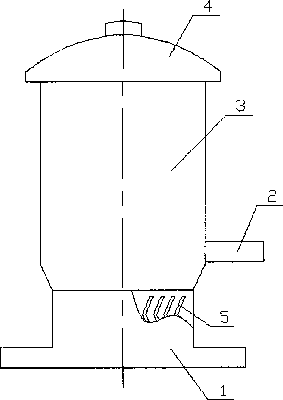
[0019] figure 1 It is a schematic diagram of the appearance of the oil-gas separator. The oil-gas separator base 1 is fixed on the cylinder block by bolts and directly communicates with the crankcase. The base 1 is equipped with a labyrinth pre-separator 5, that is, an S-shaped oil blocking plate. The upper end is connected with the main separator shell 3 and the main separator cover 4, and the air outlet pipe 2 is connected with the main separator shell 3 below.

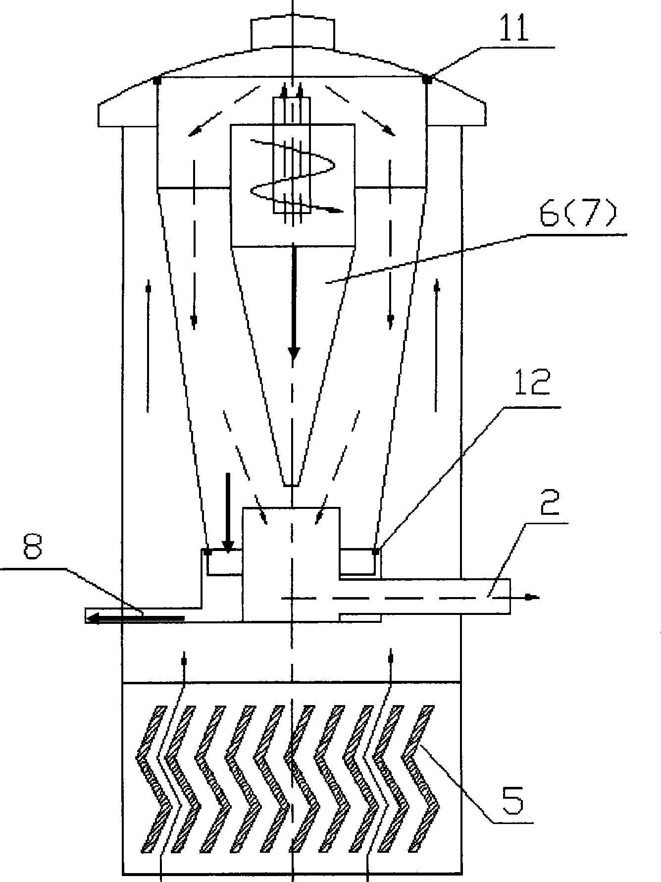
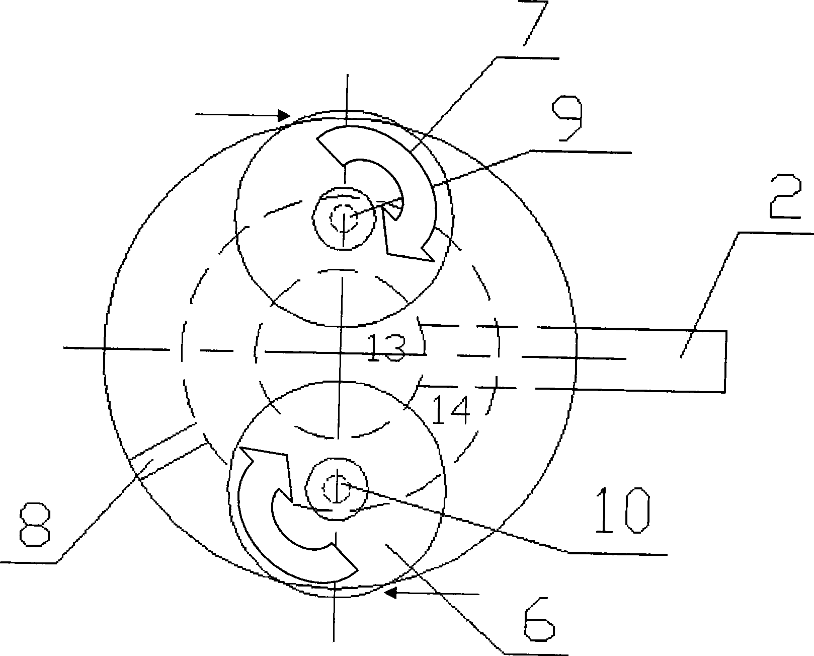
[0020] figure 2 It is a schematic diagram of the internal structure of the oil-gas separator, image 3 It is a top view inside the main separator. As shown in the figure, the mixed gas in the crankcase is first pre-separated through the labyrinth S-shaped oil baffle plate 5, and the separated oil directly flows back to the crankcase along the oil baffle plate 5, and the remaining unseparated mixed...


PUM


Abstract

The invention discloses a double-stage oil gas separator comprising a main separator, a preseparator and a base, wherein, the base is fixed on a cylinder body by bolts, and the preseparator is installed in the base and is directly communicated with a crankcase; and the preseparator is an S-shaped wavy labyrinth which comprises a plurality of S-shaped oil block bent plates. The main separator comprises a main separator housing, a main separator cover, two cyclone separators, a gas outlet pipe and an oil outlet pipe, wherein, the bottom of the main separator is sealed with the oil return part and the gas outlet part by a bottom seal packingring, and the top of the main separator is sealed with the main separator cover by a top seal packingring. The double-stage oil gas separator has novel structure, and compared with the other double-stage oil gas separators, the double-stage oil gas separator of the invention occupies little space, is in favor of overall arrangement, thoroughly separates oil and gas and not only can reduce the pollutant discharge but also can reduce the consumption of lubricating oil, thereby reducing the running cost.

Description

technical field [0001] The invention relates to a diesel engine oil-gas separator, in particular to a two-stage oil-gas separator with a labyrinth pre-separation mechanism. Background technique [0002] The oil-air separator structure of the existing engine crankcase ventilation system is either integrated into the valve chamber cover in a labyrinth type, or a general-purpose condensing oil-air separator is used. The labyrinth oil-gas separation integrated in the cover is not efficient, takes up a lot of space, and has high manufacturing costs. The condensing oil-gas separator has a short separation path for the oil-air mixture, and some of the mixture is still discharged into the atmosphere, causing air pollution, or enters the intake pipe for combustion, causing serious consequences such as poor combustion and carbon deposits on the valve. Contents of the invention [0003] In order to solve the above technical problems, the present invention provides a two-stage oil-ga...

Claims


Application Information

Patent Timeline
Patent Type & Authority Applications(China)
IPC IPC(8): F01M11/08
Inventor 刘超张士鹏王孟轲
Owner CHERY AUTOMOBILE CO LTD
Why Eureka
Try Eureka