Heat exchanger

A technology of heat exchange device and heat exchange flat tube, which is applied in the direction of heat exchanger shell, heat exchange equipment, lighting and heating equipment, etc., which can solve the problems of large heat exchanger volume and small heat exchanger volume, and achieve heat transfer The effect of large coefficient, small volume and enhanced heat transfer effect

Inactive Publication Date: 2009-06-17
SUZHOU QUTU THERMAL CONTROL SYST
View PDF0 Cites 3 Cited by
  • Summary
  • Abstract
  • Description
  • Claims
  • Application Information

AI Technical Summary

Problems solved by technology

The existing various heat exchangers are relatively large in volume, which cannot meet the requirements of some equipment for small heat exchangers

Method used


Image

  • Heat exchanger
  • Heat exchanger
  • Heat exchanger

Examples


Embodiment Construction

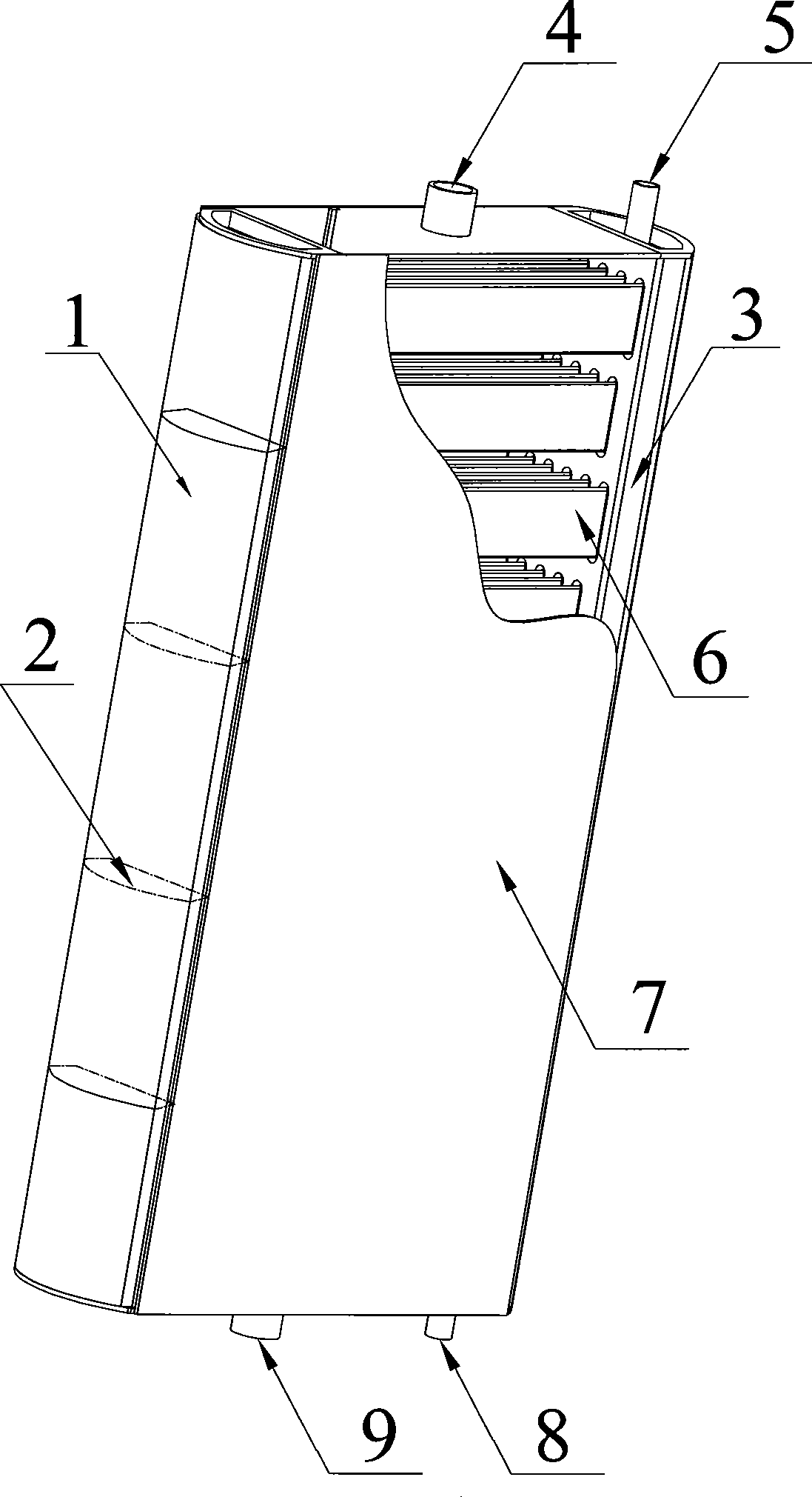
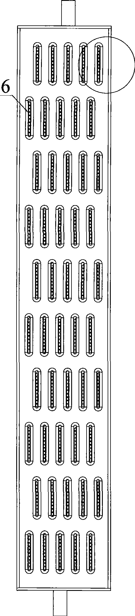
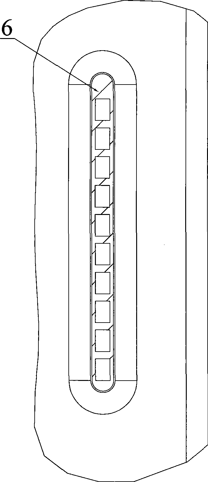
[0019] A heat exchange device such as figure 1 As shown, it includes left header 1, right header 3, heat exchange flat tube 6 and shell 7, forming a closed rectangular parallelepiped, and multiple rows of heat exchange flat tubes 6 are arranged in a rectangular shell 7 in a staggered arrangement up and down. The heating flat tube 6 is fixed to the front and rear sealing plates of the housing 7 and has reinforcing ribs. The plane of the heat exchange flat tube is parallel to the axial direction of the header. The left and right ports of the heat exchange flat tube 6 are respectively welded to the left collector. The flow pipe 1 and the right header 3 are provided with a baffle plate 2 inside the left header 1 and the right header 3, so that the left header 1, the right header 3 and the heat exchange flat tube 6 form a seal. There are also "S"-shaped circulation passages connected end to end, and there are multiple circulation passages inside the heat exchange flat tube 6; in ad...


PUM


Abstract

The invention provides a heat exchanger, which comprises a left collecting pipe, a right collecting pipe, a heat exchanging flat pipe and a shell body and forms an enclosed rectangle. Rows of heat exchanging flat pipes are staggered up and down in the rectangular shell; the plane of the heat exchanging flat pipe parallels the axial line of the collecting pipe; the left and right ports of the heat exchanging flat pipe are respectively welded on the left collecting pipe and the right collecting pipe; a baffle is arranged in the left collecting pipe and the right collecting pipe so as to form a sealed and end-to-end circulation channel between the left and right collecting pipes and the heat exchanger flat pipe, and the inside of the heat exchanger flat pipe is provided with a plurality of circulation channels; in addition, the bottom part of the shell body is provided with a fluid inlet and the upper part of the shell body is provided with a fluid outlet; an air inlet pipe and a fluid outlet pipe are communicated with the right collecting pipe or the right collecting pipe. As the invention adopts the heat exchanging flat pipe and the heat exchanging flat pipes are staggered, the heat exchanging effect of parallel flows is strengthened, the structure is quite compact and the heat exchanging efficiency is very high, thus well satisfying the fact that cooling or air-conditioning equipment requires small heat exchangers.

Description

technical field [0001] The invention relates to a heat exchange device, which belongs to the technical field of refrigeration and air conditioning. Background technique [0002] The heat exchange device is used in air conditioners to form electric compression air conditioners, chiller air conditioners, etc. Most of the heat exchangers in refrigeration and air-conditioning equipment use finned heat exchangers. The structure of this heat exchanger is that there are many thin heat exchange fins in series outside the circulating heat exchange tubes by means of mechanical expansion tubes. There are many aluminum fins or copper fins, and there is a large wind resistance when the cooling medium (such as air, etc.) flows through the gap between the fins, and it is easy to have dead angles of air flow. When using air conditioning equipment in a dusty environment (such as industrial cabinet air conditioner or car air conditioner, etc.), the dust in the air will gradually accumulate a...

Claims


Application Information

Patent Timeline
Patent Type & Authority Applications(China)
IPC IPC(8): F25B39/00F28F9/26
Inventor 刘明国
Owner SUZHOU QUTU THERMAL CONTROL SYST
Why Eureka
Try Eureka