Dry filter for refrigerator and energy-conserving refrigeration loop
A refrigeration circuit and filter technology, applied in the field of refrigerator driers and energy-saving refrigeration circuits, can solve problems such as a single function, and achieve the effects of reliable refrigeration work, reduced leakage points, and reduced maintenance.
- Summary
- Abstract
- Description
- Claims
- Application Information
AI Technical Summary
Problems solved by technology
Method used
Image
Examples
Embodiment 1
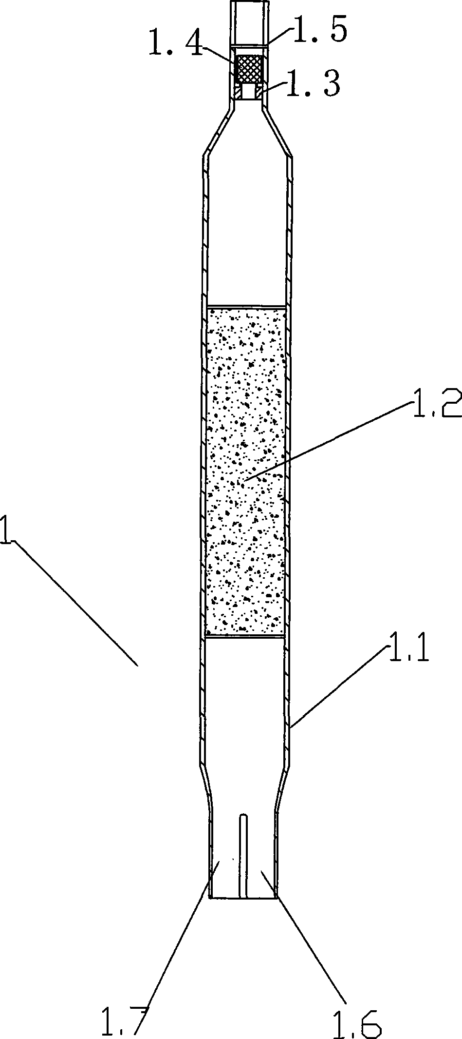
[0020] Embodiment 1: see figure 1 , the dry filter 1 for the refrigerator of the present invention comprises a filter shell 1.1 with two parallel air inlets 1.7 and 1.6, a built-in desiccant 1.2, and the gas outlet end section is closed into a thin tube section, and a one-way valve nozzle 1.3 ( The air outlet end of the valve nozzle is in the same direction as the air outlet of the filter) and the plugging rubber spool 1.4, and the outer limit ring 1.5 of the plugging spool.
[0021] In addition, the valve nozzle, the valve core and the limit structure can also be arranged on the inlet end of the filter, and can be set as one-way opening according to the working flow direction of the refrigerant gas.
[0022] It is also possible to set a one-way valve at both ends of the filter at the same time, and make the conduction and cut-off in the same direction; a spring can also be added between the spool and the spool limit (outside of the spool top opening) to improve the cut-off se...
Embodiment 2
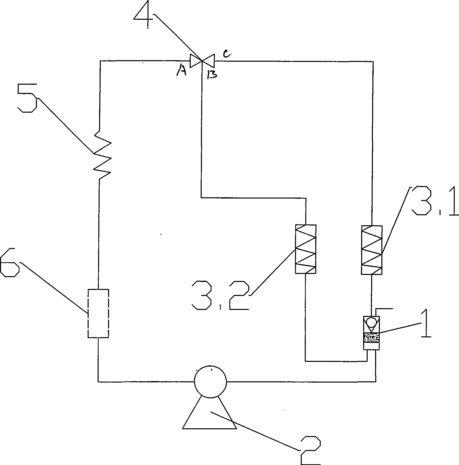
[0023] Example 2: see figure 2 , the energy-saving refrigeration circuit of the refrigerator, including a compressor 2, the outlet end is connected to the air intake end of the drier filter 1 with a check valve in embodiment 1, and the outlet end of the drier filter 1 is connected in series with the working condenser 3.1, and connected to the two The three-way solenoid valve 4 is connected to form a pressure-maintaining circuit; the other inlet end of the dry filter 1 (which can also be connected to the compressor outlet) is connected in series with the auxiliary condenser 3.2, and then connected to the two-position three-way solenoid valve 4 to form a Stop the pressure relief circuit. The pressure-holding circuit and the pressure-relieving circuit are connected in parallel and in series to the inlet end of the capillary 5, are connected in series to the evaporator 6, and return to the compressor 2 to form a refrigeration circuit.
[0024] The compressor 2 is working, the hi...
Embodiment 3
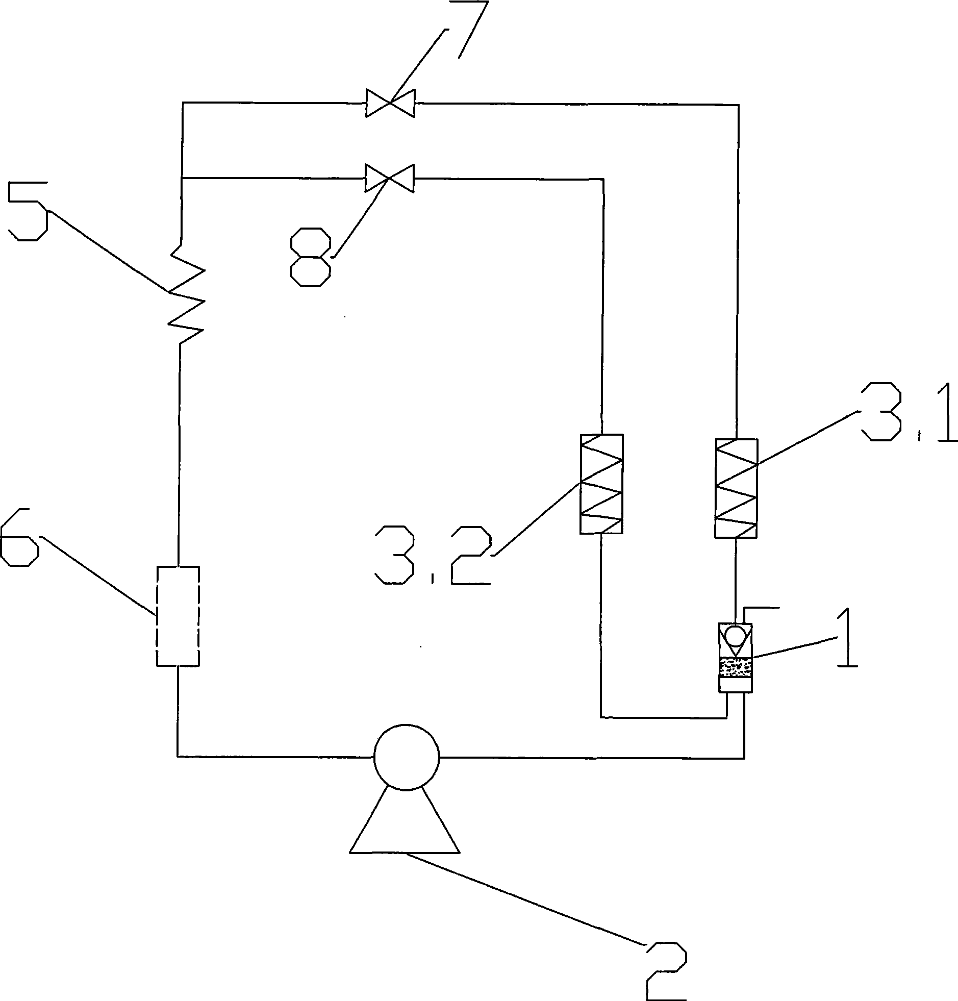
[0025] Embodiment 3: see image 3 , As in embodiment 2, wherein the two-position three-way solenoid valve 4 is replaced by two stop valves 7,8. A dry filter 1 with a check valve, a working condenser 3.1, and a stop valve 7 are connected in series to form a pressure maintaining circuit; an auxiliary condenser 3.2 connected to the output end of the compressor, and a stop valve 8 are connected in series to form a shutdown pressure relief circuit. After the pressure holding circuit and the pressure relief circuit are connected in parallel, they are connected in series to the refrigeration circuit, and the working process is the same as that in Embodiment 2.
PUM
 Abstract
Description
Claims
Application Information
 - R&D
- Intellectual Property
- Life Sciences
- Materials
- Tech Scout
- Unparalleled Data Quality
- Higher Quality Content
- 60% Fewer Hallucinations
Browse by: Latest US Patents, China's latest patents, Technical Efficacy Thesaurus, Application Domain, Technology Topic, Popular Technical Reports.
© 2025 PatSnap. All rights reserved.Legal|Privacy policy|Modern Slavery Act Transparency Statement|Sitemap|About US| Contact US: help@patsnap.com


