Isothermal lifting blade drum slag cooling machine

A technology of drum slag cooling machine and lifting plate, which is applied in the field of machinery, can solve the problems of high maintenance cost, high manufacturing cost, and easy burning of the inner cylinder, so as to increase the heat exchange area, reduce maintenance cost, and improve operation efficiency effect

Inactive Publication Date: 2011-09-07
南京科臣节能设备有限公司
View PDF0 Cites 0 Cited by
  • Summary
  • Abstract
  • Description
  • Claims
  • Application Information

AI Technical Summary

Problems solved by technology

[0003] Due to the existence of thermal resistance of the existing lifting plate, the height of the lifting plate cannot be too high, otherwise it will be seriously burned due to the high temperature environment in the cylinder, thus limiting the heat exchange effect of large-tonnage cold slag and directly causing the flow of slag reduce
[0004] At present, the blades of the lifting plate in the high temperature section of the roller slag cooling machine in the industry are mostly made of high-temperature wear-resistant alloy steel plates, the equipment manufacturing cost is high, and the heat conduction and heat transfer performance of the lifting plate blades are poor.
In addition, due to its long-term operation at high temperature, it is easy to burn and even fall off the inner cylinder, resulting in clogging of slag, so there are many equipment failures and high maintenance costs

Method used


Image

  • Isothermal lifting blade drum slag cooling machine
  • Isothermal lifting blade drum slag cooling machine
  • Isothermal lifting blade drum slag cooling machine

Examples


Embodiment Construction

[0018] The present invention will be further described below in conjunction with the accompanying drawings.

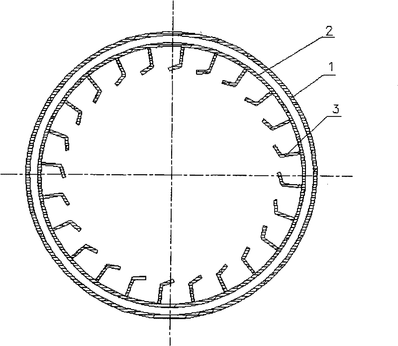
[0019] figure 1 It is a schematic diagram of the distribution structure of the lifting plates in the rotating drum of the drum cooling slag machine in the prior art;

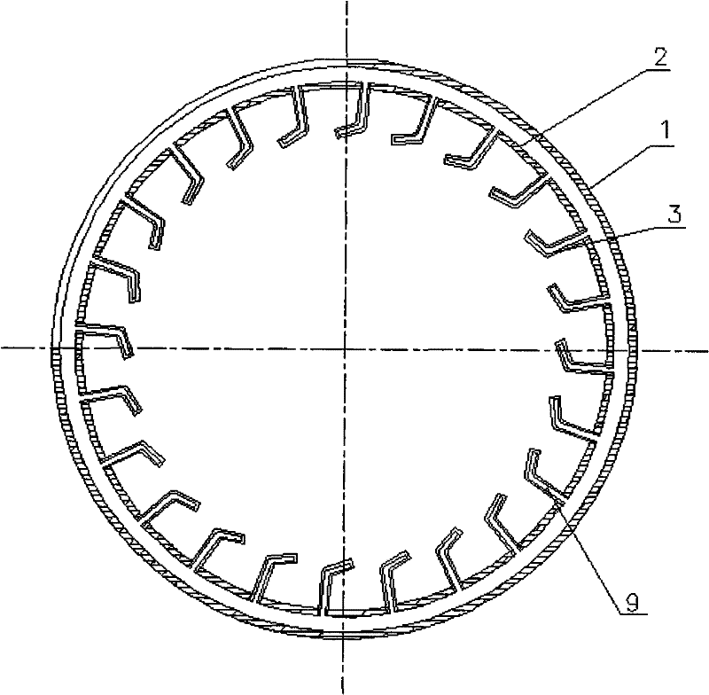
[0020] figure 2 It is a structural schematic diagram of the lifting plate in the rotating drum of the isothermal lifting plate drum slag cooling machine of the present invention.

[0021] The existing drum slag cooling machine includes a rotating drum, the rotating drum includes an inner cylinder 2 and an outer cylinder 1, the annular cavity between the inner cylinder 2 and the outer cylinder 1 is filled with cooling water, and the inner wall of the inner cylinder is provided with Multiple lifting plates 3, the multiple lifting plates are arranged spirally from one end of the inner wall of the inner cylinder to the other end, there is no cavity inside the lifting plate 3, and the top of the lifting pl...


PUM


Abstract

The invention discloses an isothermal lifting blade roller slag cooler which comprises a rotating roller comprising an inner barrel and an outer barrel. An annular cavity between the inner barrel and the outer barrel is full of cooling water; and the inner wall of the inner barrel is provided with a plurality of lifting blades which are spirally arrayed from one end of the inner wall of the innerbarrel to the other end. The invention is characterized in that all lifting blades in the rotating roller or only the lifting blade at a high temperature section in the rotating roller is provided with an inside cavity which is communicated with the annular cavity between the inner barrel and the outer barrel. As the lifting blade is designed to have the hollow structure and the inside cavity (orcavities) of the lifting blade(s) is communicated with the annular cavity between the inner barrel and the outer barrel, the heat exchange area is increased by times, the heat transfer efficiency is remarkably improved, greater amount of heat energy is taken away, and the lifting blades can increase unfolding height, therefore, slag flow rate of a large-tonnage slag cooler can be improved.

Description

technical field [0001] The invention relates to an isothermal lifting plate roller slag cooling machine used in industries such as metallurgy, electric power, and petrochemical fluidized bed boilers, and belongs to the field of mechanical technology. Background technique [0002] The drum slag cooler is mainly used for cooling the slag of the fluidized bed boiler. The slag discharge temperature of the fluidized bed boiler is about 1050°C, and it is cooled to 100°C by a slag cooler, and the cooling medium is water. The existing slag cooling machine comprises a base, a driving device, a feeding device, a discharging device, a rotating drum, and a rotary joint. The rotating drum of the drum slag cooling machine is a double-layer cylinder, the cooling water is passed through the middle of the double-layer cylinder, and the slag is removed in the inner cylinder. The conventional drum cooling slag machine is a lifting plate type drum cooling machine. There are multiple lifting p...

Claims


Application Information

Patent Timeline
Patent Type & Authority Patents(China)
IPC IPC(8): F28D11/02
Inventor 王道河
Owner 南京科臣节能设备有限公司
Why Eureka
Try Eureka