
Light beam shaper by refractometry for two-dimension laminate light source

A technology of beam shaping and refraction, applied in laser devices, semiconductor laser devices, optics, etc., can solve problems such as difficult fiber coupling output

Inactive Publication Date: 2009-06-17
INST OF SEMICONDUCTORS - CHINESE ACAD OF SCI
View PDF0 Cites 9 Cited by
  • Summary
  • Abstract
  • Description
  • Claims
  • Application Information

AI Technical Summary

Problems solved by technology

while M in the direction of the slow axis 2 Even after slow axis compression, the factor can be reduced by Z times at most, Z=slow axis direction bar laser step length / slow axis direction bar laser single light emitting area length, its value is still very large, it is difficult to achieve fiber coupling output

Method used


Image

  • Light beam shaper by refractometry for two-dimension laminate light source
  • Light beam shaper by refractometry for two-dimension laminate light source
  • Light beam shaper by refractometry for two-dimension laminate light source

Examples


Embodiment Construction

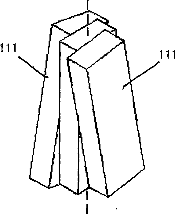
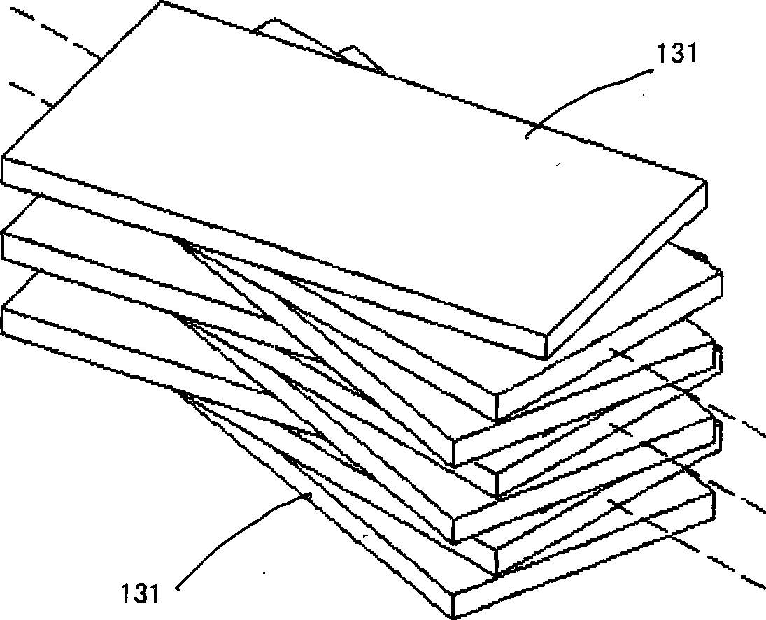
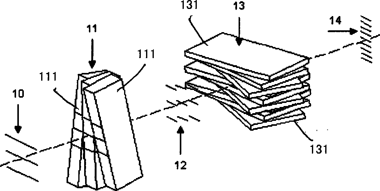
[0028] see Figure 1 to Figure 3 As shown, the present invention is a refraction beam shaper for a two-dimensional stacked light source, which is characterized in that it includes:

[0029] A first parallel flat mirror stack 11, the first parallel flat mirror stack 11 is formed by stacking a plurality of parallel flat mirrors 111, and each parallel flat mirror 111 of the first parallel flat mirror stack 11 is arranged in an X shape according to a central axis The fans are closely arranged;

[0030] The height of the first parallel flat mirror stack 11 is greater than the overall height of the shaped light source, and the width is greater than the overall width of the shaped light source;

[0031] A second parallel flat mirror stack 13, the second parallel flat mirror stack 13 is formed by stacking a plurality of parallel flat mirrors 131, the second parallel flat mirror stack 13 takes the number of parallel flat mirror stacks 11 as a period, and every A plurality of parallel...


PUM


Abstract

A light beam reshaper by refraction aiming at two-dimension laminated light source is characterized in that the light beam reshaper comprises a first parallel flat mirror pile which is stacked by a plurality of flat mirrors and a second parallel flat mirror pile which is also stacked by a plurality of flat mirrors; wherein, the first parallel flat mirror pile and the second parallel flat mirror pile are arranged in sequence along the transmission direction of light beam. The light beam reshaper by refraction aiming at two-dimension laminated light source of the invention has the advantage that after the outgoing two-dimension light beam matrix getting through the reshaper, the shining dead zone is eliminated and becomes even-distributed beam with better focusing performance.

Description

technical field [0001] The invention relates to a refraction beam shaper for a two-dimensional laminated light source, which eliminates the dead zone of the beam of the two-dimensional laminated device, improves the quality of the output beam, and improves the brightness of the output light and the performance of coupling and focusing. Background technique [0002] Since the 1980s, with the advancement of semiconductor material growth technology, laser packaging and refrigeration technology, high-power semiconductor lasers with high power, long life and high packaging density have gradually matured. In recent years, stacked semiconductor lasers with the advantages of high output power, small size, and long life have developed rapidly. They are used in many fields such as industry, scientific research, and medicine, such as industrial laser processing, welding, pumping solid-state lasers, and laser surgery It has been widely used in many aspects. However, semiconductor laser...

Claims


Application Information

Patent Timeline
IPC IPC(8): G02B27/09H01S5/40
Inventor 王翠鸾韩淋刘媛媛冯小明李伟马晓宇
Owner INST OF SEMICONDUCTORS - CHINESE ACAD OF SCI
Learn More