
Computer monitoring terminal and monitoring method

A computer monitoring and terminal technology, applied in the direction of hardware monitoring, response error generation, etc., can solve the problems of reducing the stability and reliability of the computer monitoring system, stopping work, etc.

Inactive Publication Date: 2009-06-17
HONG FU JIN PRECISION IND (SHENZHEN) CO LTD +1
View PDF0 Cites 8 Cited by
  • Summary
  • Abstract
  • Description
  • Claims
  • Application Information

AI Technical Summary

Problems solved by technology

[0003] But above-mentioned computer monitoring system also has some shortcomings, for example, computer 12 will not be able to carry out data transmission with terminal device 16 in the process of restarting of microprocessor 144, has reduced the working stability and reliability of described computer monitoring system, and when microprocessor After the device 144 is damaged, the entire computer monitoring system will stop working

Method used


Image

  • Computer monitoring terminal and monitoring method
  • Computer monitoring terminal and monitoring method

Examples


Embodiment Construction

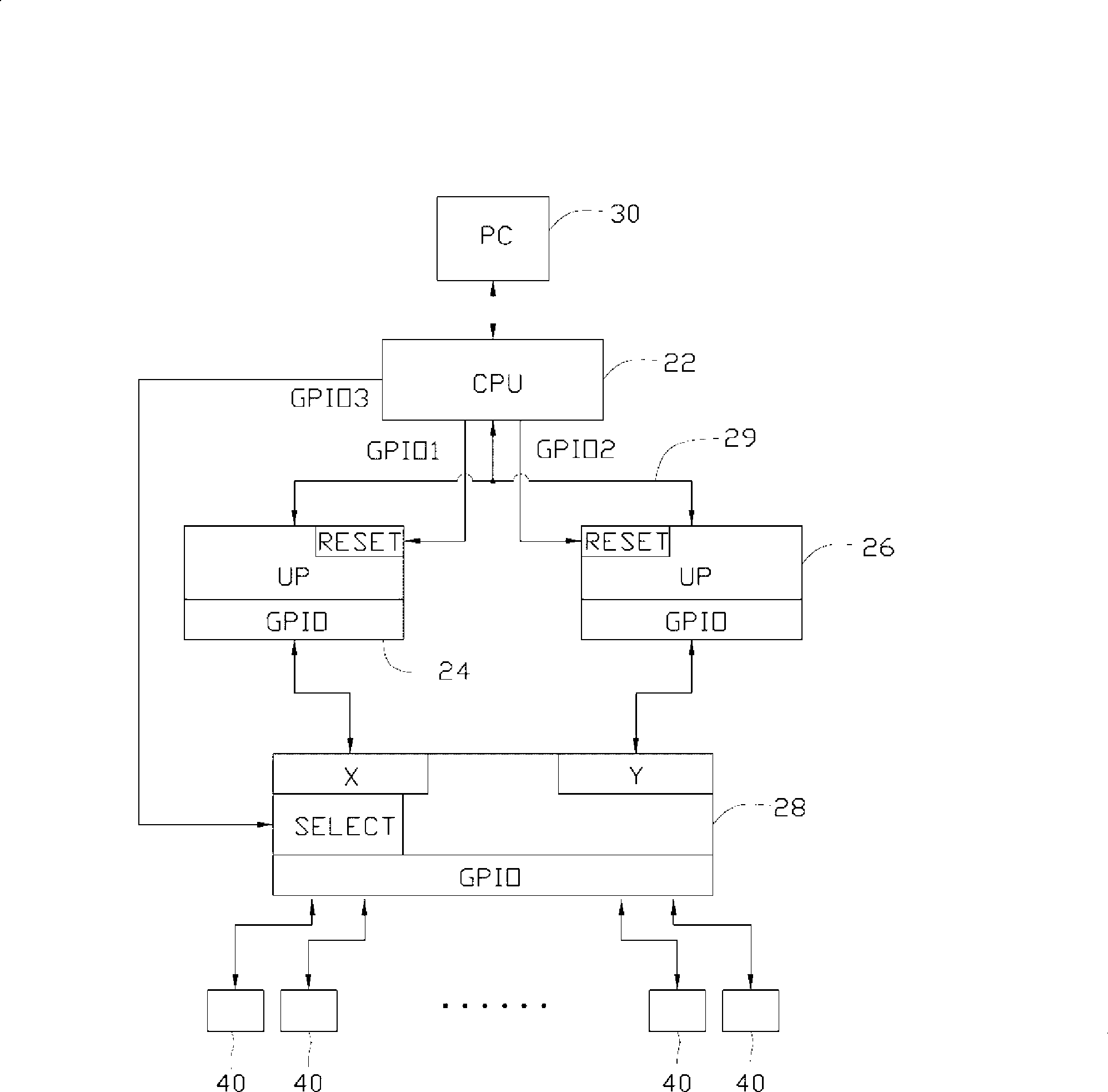
[0013] refer to figure 2 , the preferred embodiment of the computer monitoring terminal of the present invention includes a central processing unit 22, a first microprocessor 24, a second microprocessor 26 and a switch 28, and the central processing unit 22 includes three output terminals GPIO1 ~ GPIO3, a data input end and a data output end, the first and second microprocessors 24 and 26 all include an output end GPIO, a restart end RESET and an input end, and the switch 28 includes two Input terminals X and Y, an output terminal GPIO and a control terminal SELECT, the control terminal SELECT of the switch 28 can selectively switch one of its input terminals X and Y after receiving a control signal sent by the central processing unit 22 It is connected to its output GPIO.

[0014] The data input end of the central processing unit 22 is connected with a computer 30 through a serial port for data transmission, and the data output end of the central processing unit 22 is conne...


PUM


Abstract

A computer monitoring terminal comprises a central processing unit, a first microprocessor, a second microprocessor and a selective switch, the central processing unit is respectively connected with the selective switch by the first microprocessor and the second microprocessor for outputting a control signal to select one of the first microprocessor and the second microprocessor to perform data transmission, and when the microprocessor for transmitting the data works abnormally, controlling the selective switch to select the other microprocessor to perform the data transmission, and outputting a reset signal to the microprocessor which works abnormally and resetting the microprocessor which works abnormally for standby. A method applying the computer monitoring terminal is provided for implementing a fault tolerant recovering function to improve the working stability and reliability of the computer monitoring terminal.

Description

technical field [0001] The invention relates to a computer monitoring terminal and a monitoring method. Background technique [0002] refer to figure 1 , the existing computer monitoring system usually includes a computer (PC) 12, a computer monitoring terminal 14 and some terminal equipment 16 (such as temperature sensors, relays, cameras and alarms, etc.), and the computer monitoring terminal 14 includes a Central processing unit (CPU) 142 and a microprocessor (UP) 144, described central processing unit 142 is connected with described computer 12 to carry out data transmission by network, serial port or other interface, and described microprocessor 144 is through its input The / output interface GPIO is connected to the terminal device 16 , data transmission can be performed between the central processing unit 142 and the microprocessor 144 , and a reset terminal RESET of the microprocessor 144 can be controlled. In the computer monitoring system of this structure, the ce...

Claims


Application Information

Patent Timeline
Patent Type & Authority Applications(China)
IPC IPC(8): G06F11/07
CPCG06F11/30
Inventor 谢明志柯光隆
Owner HONG FU JIN PRECISION IND (SHENZHEN) CO LTD
Features
  • Generate Ideas
  • Intellectual Property
  • Life Sciences
  • Materials
  • Tech Scout
  • Unparalleled Data Quality
  • Higher Quality Content
  • 60% Fewer Hallucinations
Learn More