

Torsional vibration damper
A technology of torsional vibration and shock absorber, applied in spring/shock absorber manufacturing, spring/shock absorber, vibration suppression adjustment, etc., can solve problems such as confusion of assembly conveyor belts, and achieve the effect of limiting material input and space requirements
- Summary
- Abstract
- Description
- Claims
- Application Information
AI Technical Summary
Problems solved by technology
Method used
Image

Examples
Embodiment Construction
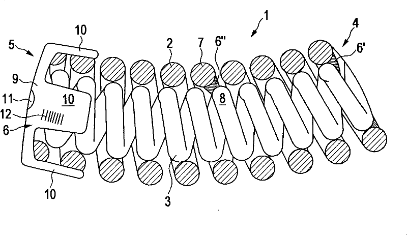
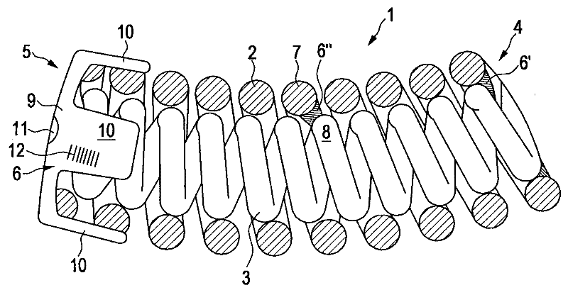
[0024] The invention is described in detail with the aid of a single figure. The figure shows a shortened arcuate energy store 1 which is installed, for example, in a dual-mass flywheel or another torsional vibration damper. it goes without saying, figure 1 The advantageous embodiments of are correspondingly also used for non-bending energy stores. In the exemplary embodiment shown, the energy store 1 has two helical springs nested inside one another, namely an outer spring 2 and an inner spring 3 . The two helical springs have two common end faces 4 , 5 which each have a differently shaped adhesive connection 6 , 6 ′ shown in an exemplary embodiment. It goes without saying that the adhesive connection 6 , 6 ′ can be implemented identically on only one end face or mixedly on both end faces 4 , 5 or uniformly on both end faces 4 , 5 . In the case of using an adhesive connection 6', this adhesive connection can also be at one place between the end faces 4, 5 between the two c...
PUM
 Abstract
Description
Claims
Application Information