Drying machine with cooling device and use method

A cooling device and dryer technology, which is used in dryers for static materials, local stirring dryers, dryers, etc., can solve the problems of mildew of materials, limitation of feeding time, and the speed of discharging can not be too fast. Enhance penetration, ensure no heat generation, and reduce the effect of material temperature

Active Publication Date: 2015-11-18
四川奥凯农装科技有限公司
View PDF6 Cites 0 Cited by
  • Summary
  • Abstract
  • Description
  • Claims
  • Application Information

AI Technical Summary

Problems solved by technology

Especially for continuous dryers, the feeding speed and discharging speed must match, and the discharging speed must not be too fast, so the supporting feeding auxiliary equipment must have a constant capacity, therefore, the feeding time is strictly limited, and further, the feeding Mildew of materials occurs from time to time during the feeding process

Method used


Image

  • Drying machine with cooling device and use method
  • Drying machine with cooling device and use method

Examples


Embodiment Construction

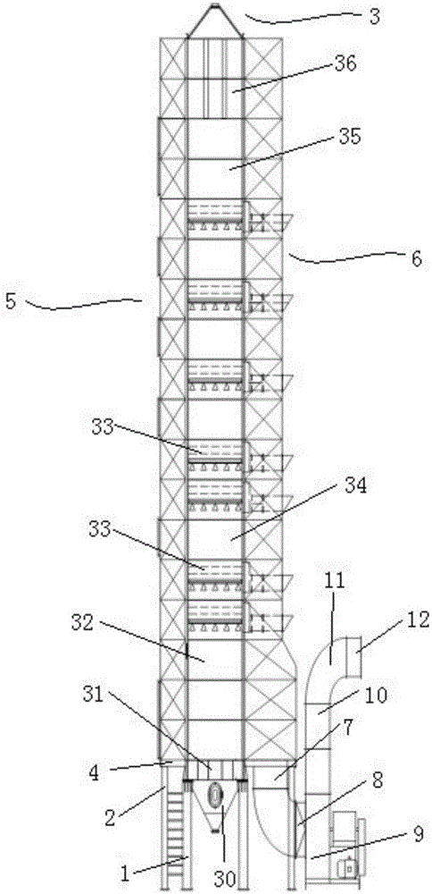
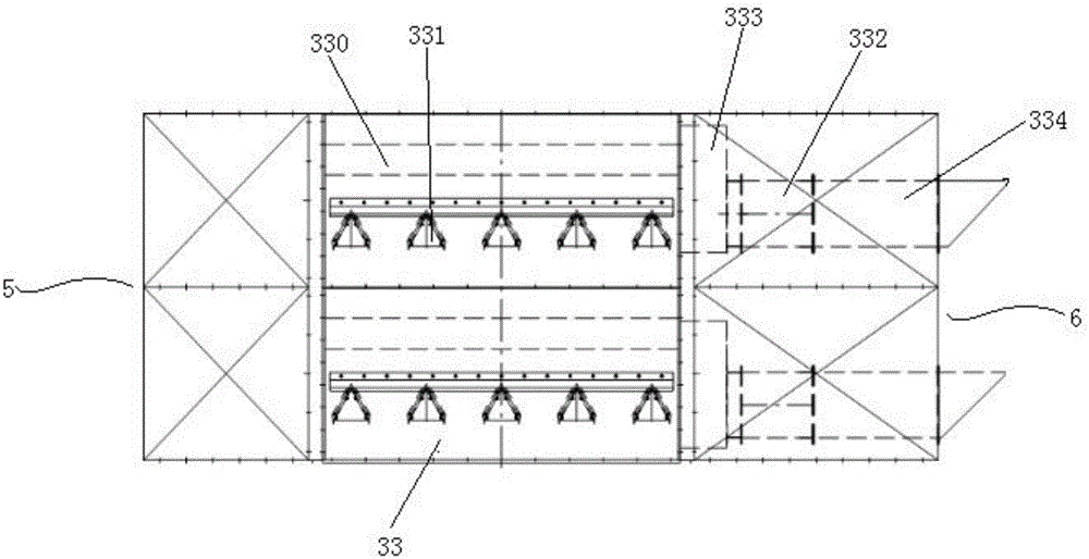
[0015] Such as figure 1 , figure 2 As shown, the present invention includes several support legs 1 that are vertically fastened on the base at equal intervals along the circumferential direction, and several support legs 1 that are vertically fastened on the base at equal intervals and are positioned on the concentric circle outside the support leg 1. The legs 2 are vertically fastened to the drying bin 3 on the leg 1, and the air inlet duct 5 that is vertically fastened on the leg 2 and located on the side of the drying bin 3 through the bracket 4 is vertically connected to the bracket 4. Straight fastening is connected on the support leg 2 and is positioned at the air outlet channel 6 on the other side of the drying bin 3 . The bottom of the air outlet channel 6 is successively connected to the air outlet straight pipe 7 and the fan reducing pipe 8 to the inlet of the induced draft fan 9, and the outlet of the induced draft fan 9 is connected to the fan outlet pipe 10, the...


PUM


Abstract

The invention relates to a drying machine with a cooling device. The drying machine comprises a drying bin connected to a base in a fastened mode, an air inlet duct disposed on one side of the drying bin and an air outlet duct disposed on the other side of the drying bin. The drying bin comprises a discharging unit, cooling units, tempering units, drying units, a stoving unit and a storage unit, wherein the discharging unit is located at the bottom end of the drying bin; the cooling units are arranged on the discharging unit; the tempering units and the drying units are sequentially arranged on the cooling units in an alternative mode; the stoving unit and the storage unit are arranged on the tempering units or the drying units in sequence. The upper portion in each tempering unit is provided with an upper ventilation duct communicated with the air inlet duct. The portion, under the corresponding upper ventilation duct, in each tempering unit is provided with a plurality of lower ventilation ducts communicated with the atmosphere. A fan communicated with the corresponding upper ventilation duct is arranged in the inner portion, corresponding to each tempering layer, of the air outlet duct. An air outlet of each fan penetrates through the air outlet duct to be communicated with the atmosphere.

Description

technical field [0001] The invention relates to a drying device, in particular to a drying machine with a cooling device and a usage method. Background technique [0002] At present, the large dryers used in the material drying process can be divided into continuous type and batch type according to the operation mode. The environment used by the dryer has the characteristics of high material humidity and high air temperature. And generally speaking, the larger the dryer bin capacity, the longer the feeding time required. Relevant studies have shown that due to the characteristics of the environment in which the dryer is used and the capacity of the dryer, the material is easily molded during the process of feeding the material into the dryer using a conveying device. Relevant test data show that rice will generate heat in about half an hour during the feeding process, and mildew will occur in 2 hours. Especially for continuous dryers, the feeding speed and discharging spe...

Claims


Application Information

Patent Timeline
Patent Type & Authority Applications(China)
IPC IPC(8): F26B9/06F26B25/00
Inventor 贾生活郭静福王润贤
Owner 四川奥凯农装科技有限公司
Why Eureka
Try Eureka