A windproof and fall-resistant sign

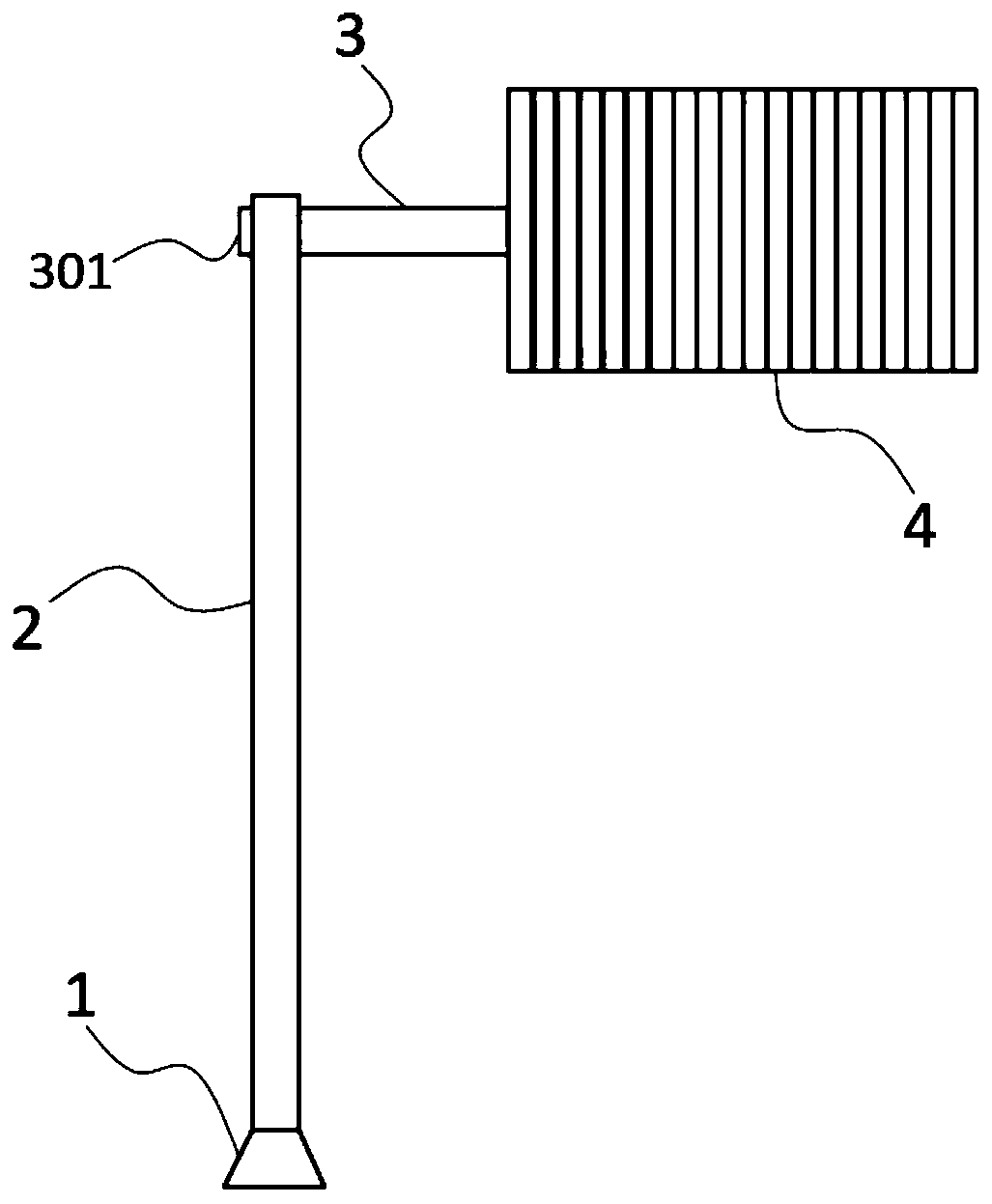
A technology of signs and support rods, which is applied to display devices, signs, instruments, etc., can solve the problems that the area of ​​the signs is too large, which is easy to cause potential safety hazards and traffic accidents, so as to avoid potential traffic safety hazards, reduce maintenance costs, and prevent deformation effect

Active Publication Date: 2020-04-28
浙江亚泰电力科技有限公司
View PDF9 Cites 0 Cited by
  • Summary
  • Abstract
  • Description
  • Claims
  • Application Information

AI Technical Summary

Problems solved by technology

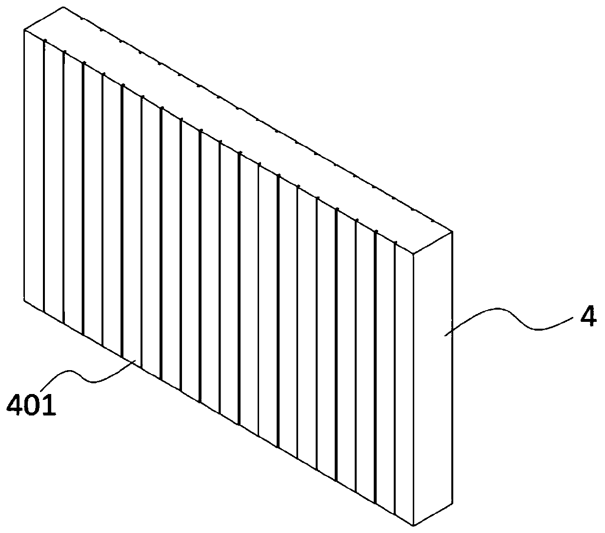
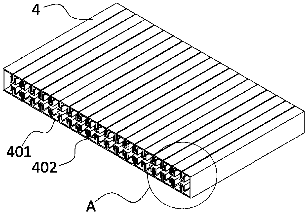
[0003] The purpose of the present invention is to provide a windproof and anti-falling signboard. First U-shaped grooves are arranged side by side through the bottom of the signboard; a second U-shaped groove is sleeved above the edge of the adjacent first U-shaped groove; A return channel is formed between the U-shaped groove and the second U-shaped groove, and a spring is installed on the inner wall of the support rod to connect and fix with one side of the connecting rod, which solves the problem that the existing signs are too large to cause cheap, The problem of deformation is likely to cause safety hazards and traffic accidents

Method used


Image

  • A windproof and fall-resistant sign
  • A windproof and fall-resistant sign
  • A windproof and fall-resistant sign

Examples


Embodiment Construction

[0023] The following will clearly and completely describe the technical solutions in the embodiments of the present invention with reference to the accompanying drawings in the embodiments of the present invention. Obviously, the described embodiments are only some, not all, embodiments of the present invention. Based on the embodiments of the present invention, all other embodiments obtained by persons of ordinary skill in the art without creative efforts fall within the protection scope of the present invention.

[0024] In describing the present invention, it is to be understood that the terms "opening", "upper", "lower", "thickness", "top", "middle", "length", "inner", "surrounding" etc. Indicating orientation or positional relationship is only for the convenience of describing the present invention and simplifying the description, and does not indicate or imply that the components or elements referred to must have a specific orientation, be constructed and operated in a sp...


PUM


Abstract

The invention discloses a wind-preventing and falling-resisting indicating plate, and relates to the field of manufacturing of indicating plates. The wind-preventing and falling-resisting indicating plate comprises a base, a supporting rod, a connecting rod and an indicating plate body, wherein the supporting rod is fixedly connected to the upper surface of the base; penetrating grooves are formedin one end of the surface of the supporting rod; a clamping block is arranged on one end surface of the connecting rod, and is in interference fit with the penetrating grooves; the clamping block isconnected with the inner wall of the supporting rod through springs; first U-shaped grooves are formed in the bottom of the indicating plate side by side; a second U-shaped groove is formed in edges of every two adjacent first U-shaped grooves in a sleeving manner; a return passage is formed between each first U-shaped groove and the corresponding second U-shaped groove. According to the wind-preventing and falling-resisting indicating plate disclosed by the invention, a return passage is formed between each first U-shaped groove and the corresponding second U-shaped groove, so that wind can uniformly penetrate through the wind-preventing and falling-resisting indicating plate, the resistance on the wind-preventing and falling-resisting indicating plate in strong wind is reduced, the phenomenon that the wind-preventing and falling-resisting indicating plate is deformed is effectively avoided, and the traffic safety hidden dangers are avoided.

Description

technical field [0001] The invention belongs to the field of sign manufacturing, in particular to a windproof and fall-resistant sign. Background technique [0002] At the entrance of the construction site, scaffolding, entrances and exits, stairs, hollows, bridges, tunnels, edges of foundation pits, roads, etc., signs are usually set up to guide people passing by. . However, in some existing signboards, the connection between the signboard and the support pole is not firm, and under the action of external forces such as strong winds, the signboard is often easily shifted on the support pole, so that people cannot directly see the signboard If the content on the signboard is displayed, there will be a great potential safety hazard; in severe cases, it may lead to the collapse of the signboard and cause serious traffic accidents. Contents of the invention [0003] The purpose of the present invention is to provide a windproof and anti-falling signboard. First U-shaped gro...

Claims


Application Information

Patent Timeline
Patent Type & Authority Patents(China)
IPC IPC(8): G09F7/08G09F7/18G09F7/06
CPCG09F7/06G09F7/08G09F7/18
Inventor 袁先念
Owner 浙江亚泰电力科技有限公司
Why Eureka
Try Eureka