Combined material packaging and feeding method thereof
A material feeding method and material technology, which are applied to beverage preparation devices, cooking utensils, household appliances, etc., can solve the problems of large volume, complex structure, and not suitable for use as a large-scale turnover packaging.
- Summary
- Abstract
- Description
- Claims
- Application Information
AI Technical Summary
Problems solved by technology
Method used
Image
Examples
Embodiment 1
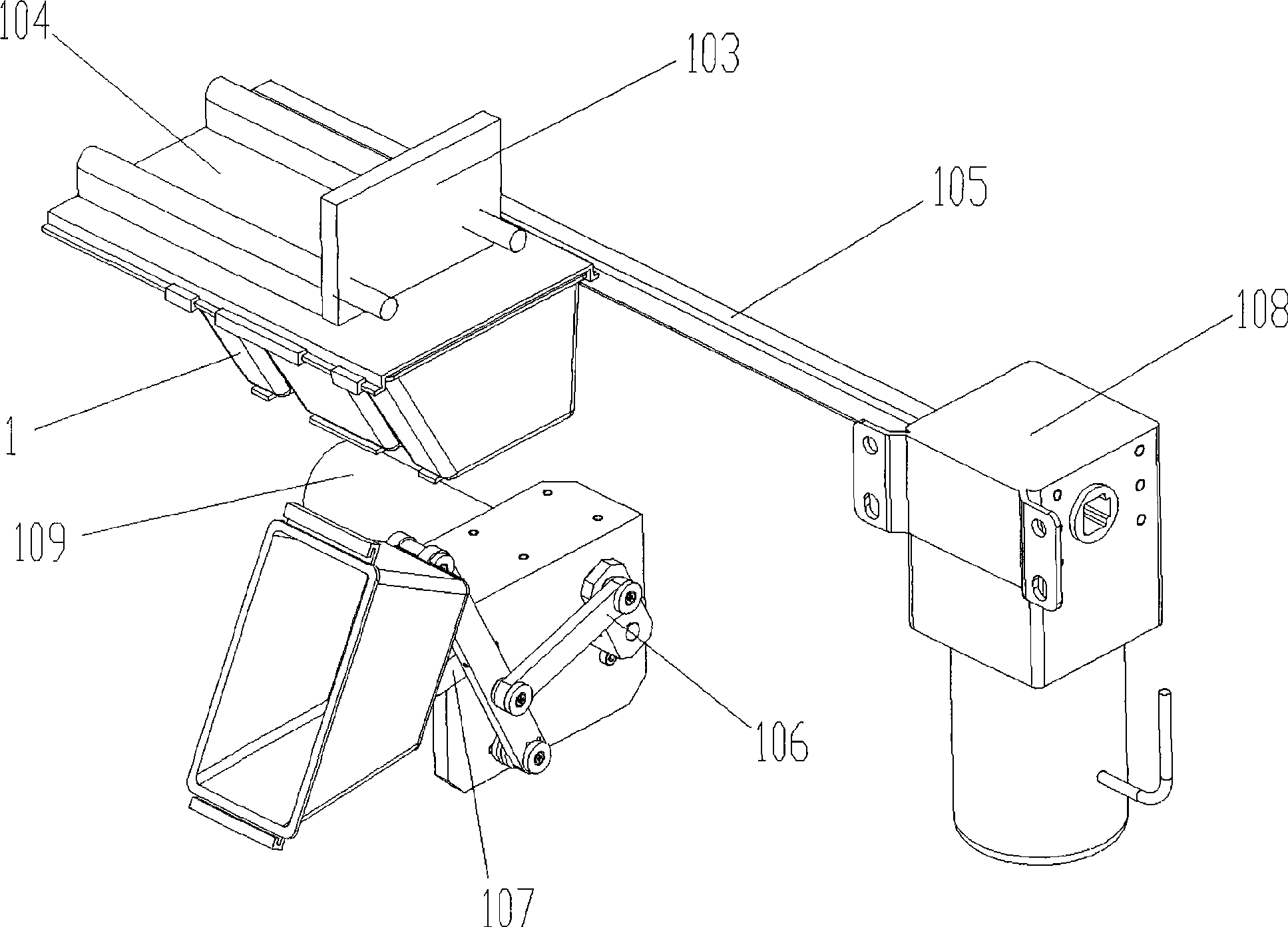
[0079] Please refer to figure 1 , the combination material box includes four material packaging units (hereinafter referred to as sub-material boxes). The sub-material box 1 adopts a free combination type, and the sealing device and the connection device of each sub-material box 1 are the same sealing plate 104, and the sealing plate 104 is provided with a fixing device. The longitudinal feeding of the sub-boxes is driven by the motor 108 through the rack 105 . During feeding, the sealing plate 104 is fixed on the bracket 103 , and the longitudinal drive of the motor 108 drives the sub-material box 1 to slide on the sealing plate 104 , and the sliding distance is the width of the sub-material box 1 . When the sub-box 1 slides, its front end slides into the gripping mechanism 107 , and its rear end just falls off the sealing plate 104 . After falling off, the turning and feeding of the sub-box 1 is driven by the motor 109 through the crank-link-rocker mechanism 106 .
Embodiment 2
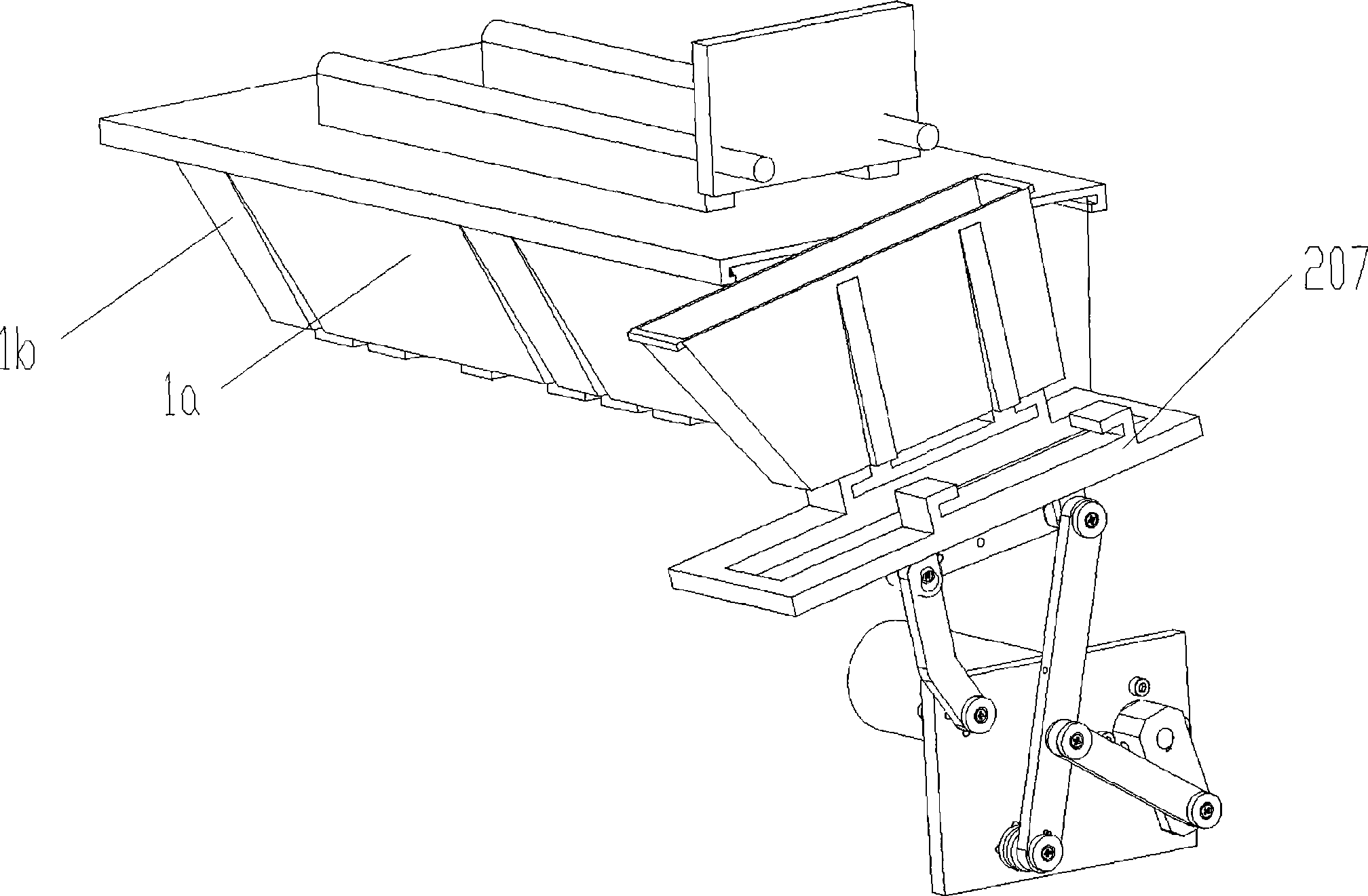
[0081] Please refer to figure 2 , the improvement of this embodiment relative to Embodiment 1 lies in the box cover structure and the grabbing mechanism. There is a groove in the front of the material box in Example 1, and the material may accumulate in the groove during feeding, which makes cleaning more difficult; because the width of the main material box 1a and the auxiliary material box 1b is very different, if a single claw is used to grab , for the main material box 1a, only one side of the bottom surface of the main material box 1a can be grasped, so that the main material box 1a itself will have a large torque. In order to solve this problem, a two-claw grasping mechanism 207 is adopted: when When grabbing the auxiliary material box, use the claw on the left in the figure to grab it. When the auxiliary material box is finished and reset, under the action of the back thrust, the auxiliary material box 1b falls from the gap in the middle of the grasping mechanism 207; ...
Embodiment 3
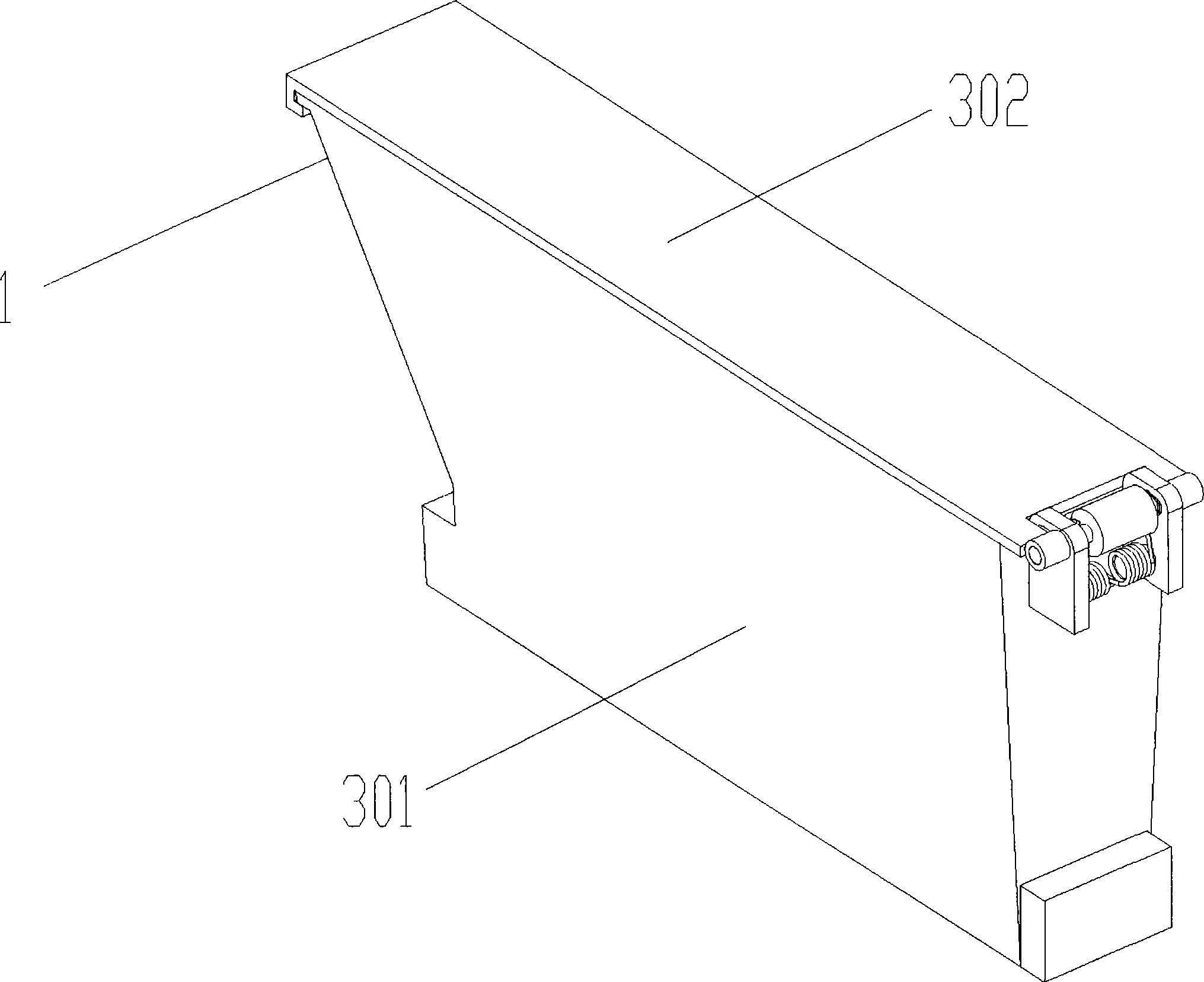
[0083] Please refer to Figure 3 to Figure 7 , each sub-box 1 is mounted in a frame 32 through a clip 31, thereby forming an integral combined material box 2.
[0084] The sub-box 1 includes a box body 301 and a box cover 302 , and the box cover 302 and the box body 301 are connected by a rotating shaft 303 . In the sealed state, the buckle 308 is buckled on the box body 301 by the force of the torsion spring 304. When the cover is opened, the rotating shaft 303 moves forward along the chute 306 by the force exerted on the drum 305, thereby opening the box cover 302 .
[0085] The cover opening mechanism 300 of the sub-box 1 includes a crank-slider mechanism 3001, a rocker 3002, a moving shaft 3003 and a fixed shaft 3004. During the downward turning process of the sub-box 1, the crank-slider mechanism 3001 is driven to move, that is, the moving shaft 3003 It rotates around the fixed axis 3004, thereby driving the rocker 3002 to rotate and push the roller 305 on the sub-box 1...
PUM
 Abstract
Description
Claims
Application Information
 - R&D
- Intellectual Property
- Life Sciences
- Materials
- Tech Scout
- Unparalleled Data Quality
- Higher Quality Content
- 60% Fewer Hallucinations
Browse by: Latest US Patents, China's latest patents, Technical Efficacy Thesaurus, Application Domain, Technology Topic, Popular Technical Reports.
© 2025 PatSnap. All rights reserved.Legal|Privacy policy|Modern Slavery Act Transparency Statement|Sitemap|About US| Contact US: help@patsnap.com


