Passive pin valve

A passive, needle valve technology, applied in the field of pressure injection molding equipment, can solve the problems of poor structural strength of the needle valve, decreased pressure transmission capacity, poor pressure transmission, etc., to improve work performance and service life, and improve strength and structural stability , The effect of improving the pressure transmission performance

Inactive Publication Date: 2009-07-01
SHANGHAI MOZOI PRECISION INSTR CO LTD
View PDF0 Cites 8 Cited by
  • Summary
  • Abstract
  • Description
  • Claims
  • Application Information

AI Technical Summary

Problems solved by technology

[0006] 1. The structure strength of the needle valve is poor,
[0007] The shunt channel adopts the annular seam structure 307 on the front shunt shuttle 302 and the rear shunt shuttle 305. The strength and structural stability of this thin-walled structure are very poor, especially in the limited space where miniaturization is required. , causing the connection between the nozzle head and the valve body to become a double-thin-walled threaded connection, resulting in insufficient overall strength of the needle valve to meet the injection requirements under higher pressure conditions, see figure 1 , Figure 3a , Figure 3b
[0008] 2. Poor pressure transmission,
[0010] The force transmission surface of the above-mentioned needle valve is on the conical surface 303a of the valve needle 303 near the injection port of the needle valve, and the injection port is the part 101 where the needle valve contacts the mold, see figure 1 , the heat loss of the needle valve at this place is very fast, and because the space around the force transmission surface of the valve needle is very narrow, the heat capacity of the fluid at this place is very small, which speeds up the temperature drop at this place, resulting in the fluidity of the local fluid Very poor, according to the principle of fluid mechanics, the pressure transmission capacity here drops sharply, and the temperature at the contact point between the needle valve and the mold will be affected by uncertain factors and become un

Method used


Image

  • Passive pin valve
  • Passive pin valve
  • Passive pin valve

Examples


Embodiment Construction

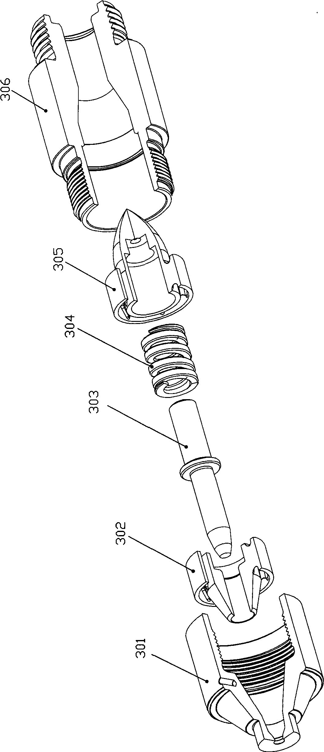
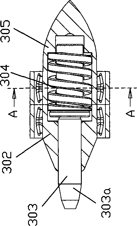
[0067] See Figure 5 ~ Figure 11b , The passive needle valve of the present invention includes a valve nozzle 1, one end of which is a cone with a central injection port 11, and the other end has a cavity structure 12; the first flow channel docking body 2 is installed in the valve nozzle 1 cavity In the body structure 12, a central through hole 21 corresponding to the central injection port 11 of the valve nozzle 1 is opened; and the first flow channel docking body 2 is also provided with three central through holes beside the central through hole 21 The sub-flow passages 22, 23, 24 that intersect with the 21 ports and communicate with the center injection port 11 of the valve nozzle are distributed symmetrically along the circumference of the center injection port 11 of the valve nozzle;

[0068] The second flow passage docking body 3, one end of which abuts against the first flow passage docking body 2 in the cavity structure 12 of the valve nozzle 1, and is threadedly connecte...


PUM


Abstract

The invention relates to a passive type pin valve. The pin valve comprises a valve nozzle, a first flow passage interconnecting body, a second flow passage interconnecting body, a valve pin, a push rod, a spring, a pouring port connecting piece and a flange disc; one end of the valve nozzle is provided with a cone body with a central feed injection port; the other end of the valve nozzle has a cavity body structure; the first flow passage interconnecting body and the second flow passage interconnecting body are arranged inside the cavity body structure of the valve nozzle and provided with central pylomes; the side of each pylome is also provided with at least one shunting passage communicated with the central feed injection port of the valve nozzle; the valve pin is arranged in the central feed injection port of the valve nozzle and the central pylome of the first flow passage interconnecting body; the push rod is arranged inside a cavity body of the second flow passage interconnecting body and is of an inverse T type; one end of the push rod is supported against one end of the valve pin; the spring is sleeved on a push rod body; one end of the spring is supported against the T type end; one side end of the pouring port connecting piece is provided with a cavity body and is sleeved at one end of the second flow passage interconnecting body; the pouring port connecting piece is provided with a central feed port which is communicated with a port of the shunting passage of the second flow passage interconnecting body; and the flange disc is sleeved on the pouring port connecting piece. The passive type pin valve adopts thread connection between parts, can meet the requirement of pressure injection molding and can automatically complete the action of opening or closing the valve along the change of fluid pressure.

Description

Technical field [0001] The present invention relates to pressure injection molding equipment, in particular to a passive needle valve. Background technique [0002] Passive needle valves are used for pressure injection molding of resins, rubbers, gels, synthetic materials (mixed plastics, binders and powdered non-ferrous metals, etc.). [0003] See figure 1 , Which shows the needle valve nozzle 30 of Japan Fraser Co., Ltd., which is set in an injection mold, wherein the mold core plate 10 and the mold cavity plate 20 form a cavity 100, and the needle valve type nozzle The nozzle 30 is connected to the nozzle 50 of the injection molding machine. [0004] See figure 2 , Figure 3a , Figure 3b , The needle valve nozzle 30 includes a nozzle head 301, a front splitter shuttle 302, a valve needle 303, a spring 304, a rear splitter shuttle 305, and a valve body 306; the front splitter shuttle 302 and the rear splitter shuttle 305 are provided with an annular seam structure 307, as In...

Claims


Application Information

Patent Timeline
IPC IPC(8): B29C45/28B29C45/73
Inventor 高建鸣
Owner SHANGHAI MOZOI PRECISION INSTR CO LTD
Why Eureka
Try Eureka