
Crawler crane

A technology of crawler crane and rotating frame, applied in the field of layout, can solve problems such as cost increase, and achieve the effects of improving transportability, easy operation, and reducing the radius of rotation

Active Publication Date: 2009-07-01
KOBELCO CONSTR MASCH CO LTD
View PDF4 Cites 0 Cited by
  • Summary
  • Abstract
  • Description
  • Claims
  • Application Information

AI Technical Summary

Problems solved by technology

However, if such noise countermeasures are taken, there is a problem of cost increase

Method used


Image

  • Crawler crane
  • Crawler crane
  • Crawler crane

Examples


Embodiment Construction

[0014] Hereinafter, embodiment which is a preferable form for carrying out this invention is demonstrated based on drawing.

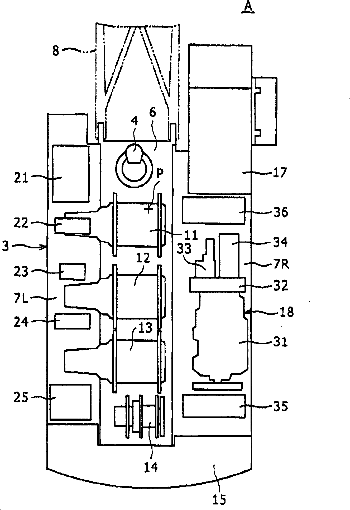
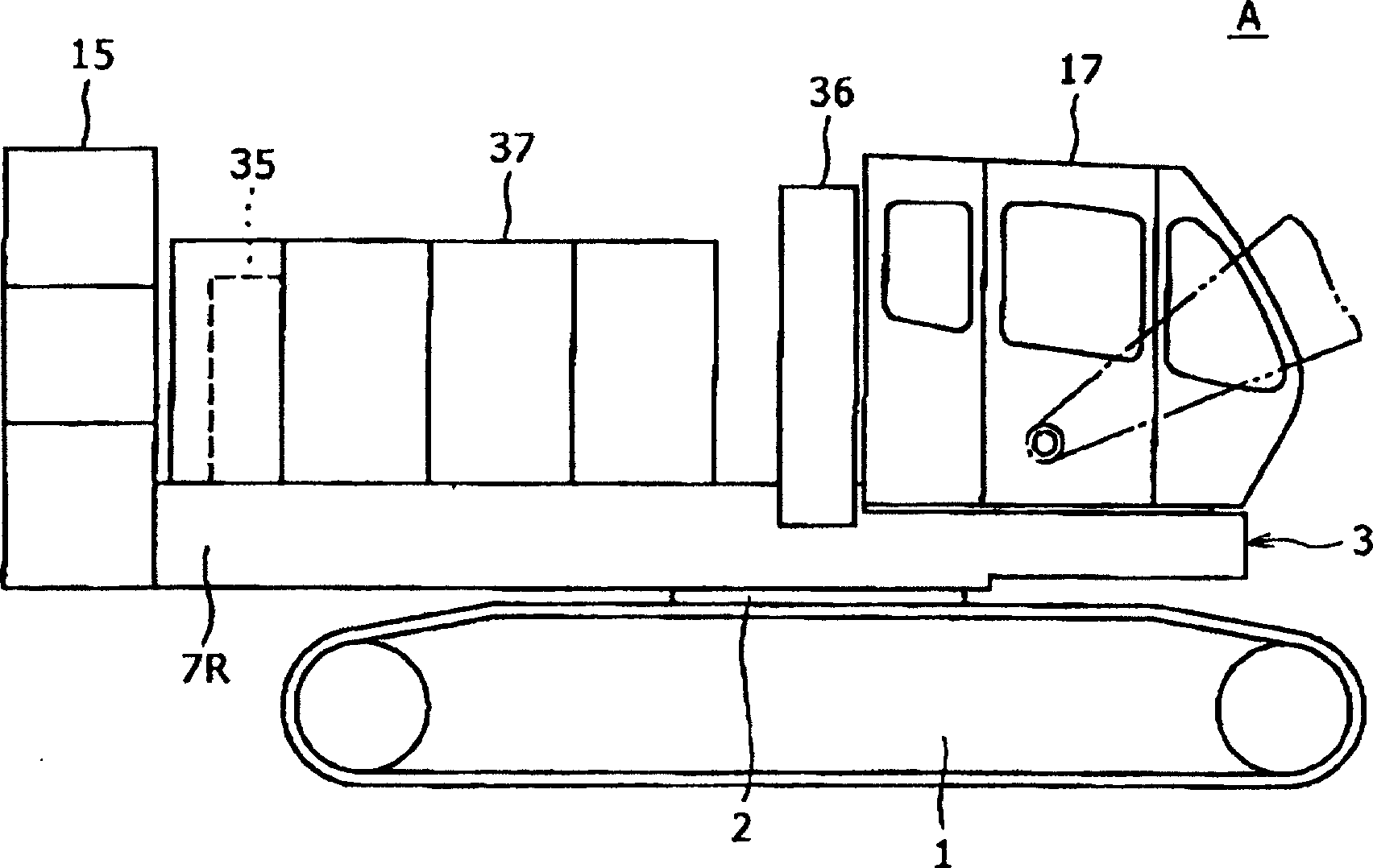
[0015] figure 1 and figure 2 The overall structure of the crawler crane A according to one embodiment of the present invention is shown. In this crawler crane A, a revolving upper body 3 is rotatably mounted on a traveling lower body 1 via a swivel device 2 . Although not shown in the figure, the rotating device 2 rotates the upper revolving body 3 around the rotation center point P by the operation of the revolving motor 4 .

[0016] The revolving superstructure 3 includes, as its frame structure, a revolving frame 6 extending in the front-rear direction at a central portion, and left and right deck frames 7L, 7R respectively attached to left and right sides of the revolving frame 6 . On the front end of the rotating frame 6, the base end of the boom 8 is swingably supported. From the vicinity of the rotation center point P of the rotating frame 6...


PUM


Abstract

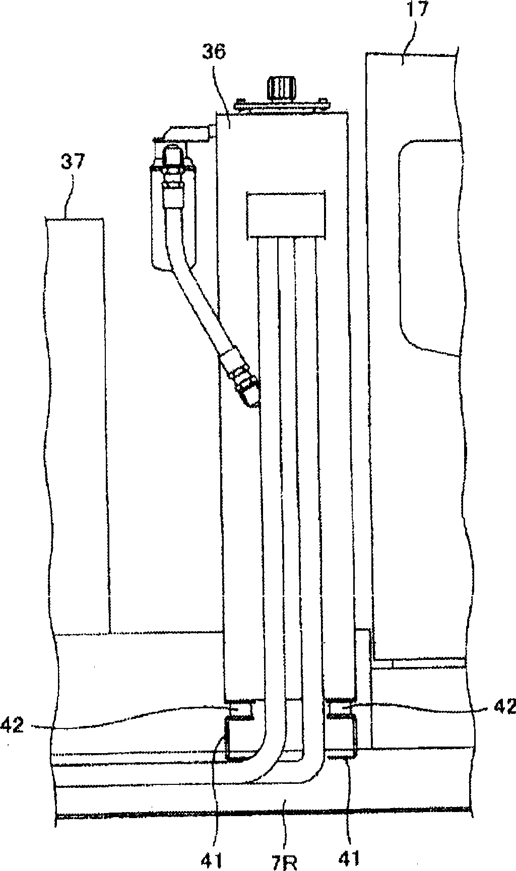
In a crawler crane of the present invention, a plurality of winches 11-14 for winding wire ropes are disposed on a rotating frame 6 of an upper rotating body 3 in a row in a plane view. A cabin 17 and a power unit 18 are disposed on the front and rear portions of either a right side or a left side of the rotating frame 6 of the upper rotating body 3. A working oil tank 36 of the power unit 18 is disposed between the cabin 17 and a driving section 31-34 of the power unit and in close proximity to a rear surface of the cabin 17. The working oil tank 36 is formed in a size which covers the substantially whole area of the rear surface of the cabin 17. In the crawler crane of the present invention, it is possible to take an anti-sound measure for the cabin to a satisfactory extent without causing cost increase. In the crawler crane of the present invention, moreover, it is possible to improve the transportability because the width of the upper rotating body can be shortened.

Description

technical field [0001] The present invention relates to a crawler crane, and more particularly to a layout in which a cab, a power unit, and the like are arranged on an upper revolving body. Background technique [0002] Generally, the upper revolving body of a crawler crane includes, as a frame structure, a revolving frame extending in the front-rear direction at a central portion, and left and right deck frames respectively attached to left and right sides of the revolving frame. As an example of such a crawler crane, there is, for example, JP-A-2005-314106 (US2007 / 0175849A1). In this example, the base end of the cantilever is swingably supported on the front end of the rotating frame. In addition, a plurality of capstans for winding a work rope for winding up or down a hook suspended from the front end of the boom are arranged in a row in front and behind in a plan view on the revolving frame. In addition, generally, a cab is arranged on one deck frame sandwiching the r...

Claims


Application Information

Patent Timeline
Patent Type & Authority Applications(China)
IPC IPC(8): B66C23/62B66C23/36
CPCB66C23/36B66C23/62
Inventor 小林丰
Owner KOBELCO CONSTR MASCH CO LTD
Learn More