Optical device containing refrigeration chip

A technology for cooling chips and light-emitting devices, applied in electrical components, electrical solid-state devices, circuits, etc., can solve problems such as reduced benefits, damaged components, and impacted benefits.

Inactive Publication Date: 2009-07-01
UNION OPTRONICS CORP
View PDF1 Cites 0 Cited by
  • Summary
  • Abstract
  • Description
  • Claims
  • Application Information

AI Technical Summary

Problems solved by technology

On the other hand, the injection current of the laser diode must be greater than the critical current density, which is related to the interface temperature and indirectly affects the efficiency
When operating at high temperature, the critical current increases, the benefit decreases, and even the components are damaged

Method used


Image

  • Optical device containing refrigeration chip
  • Optical device containing refrigeration chip
  • Optical device containing refrigeration chip

Examples


Embodiment Construction

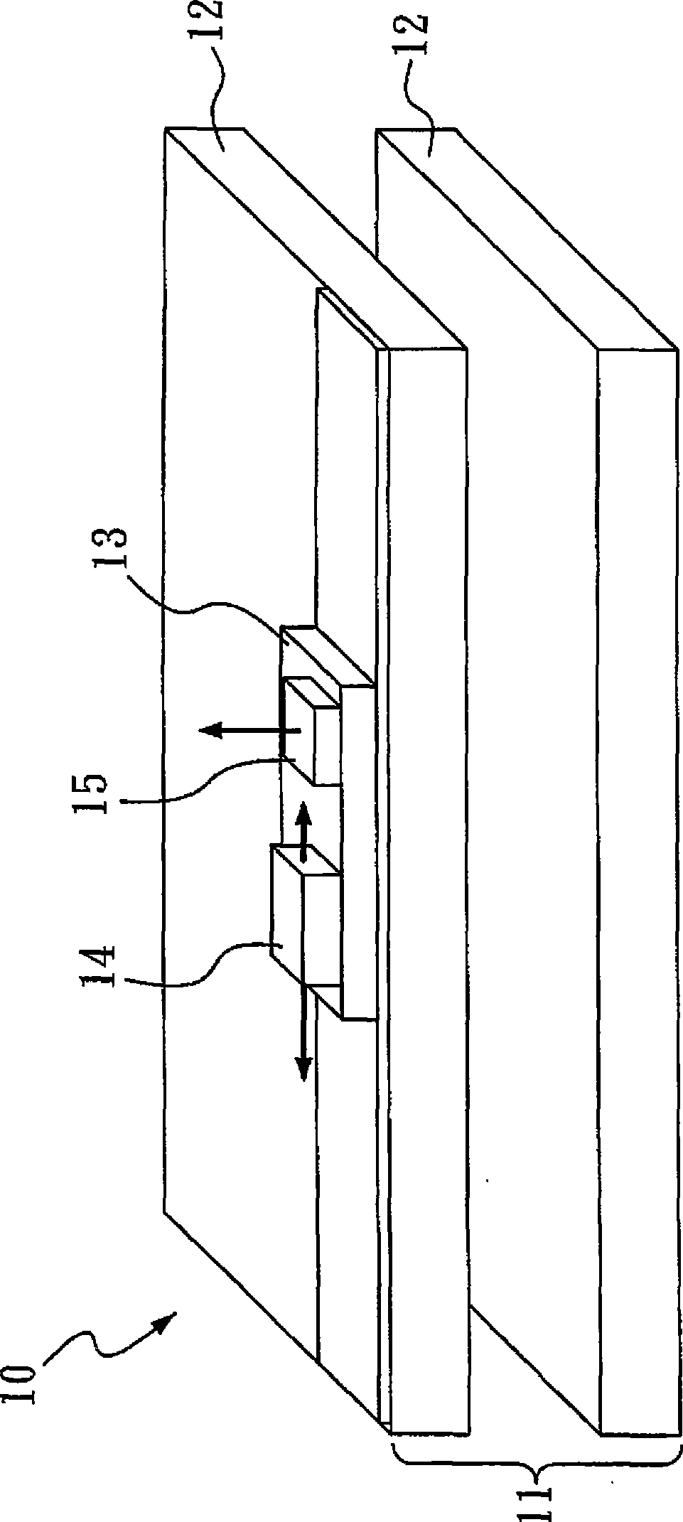
[0015] According to a preferred embodiment of the light-emitting device of the present invention, it may include a main base, and the main base includes a cooling chip, and each side of the cooling chip has a substrate, at least one of which is There is a submount on the substrate, and the submount has one or more light emitting diode chips and one or more laser diode chips.

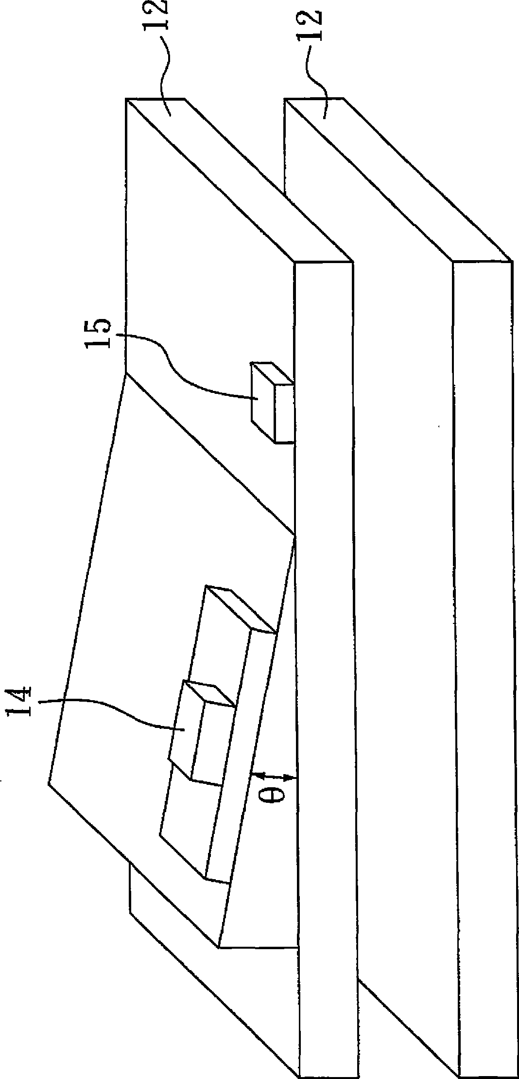
[0016] figure 1 Shown is the first embodiment, the light-emitting device 10 has a cooling chip (TE cooler) 11 on the light-emitting device, a substrate 12 is provided on both sides of the cooling chip, and a substrate 12 is provided on one side of the cooling chip. One or more sub-bases 13 are connected with the laser diode chip 14 and the light emitting diode chip 15, that is, the laser diode chip 14 and the light emitting diode chip 15 are arranged on the cooling chip, so that the laser diode chip 14 and the light emitting diode chip 15 The heat dissipation path is the same.

[0017] The material of ...


PUM


Abstract

The invention discloses a lighting device, which at least comprises a refrigeration chip, wherein the refrigeration chip is provided with a or a plurality of a laser diode chips and a or a plurality of lighting diode chips, wherein at least a laser diode and a lighting diode are arranged on the base. The lighting device can have characteristic illuminating of the laser diode when an extremely narrow spectrum frequency bandwidth is needed, and characteristic illuminating of the lighting diode which has better heat dissipating characteristics when the extremely narrow spectrum frequency bandwidth is not needed.

Description

technical field [0001] The present invention relates to light emitting devices. Specifically, the invention is a light-emitting device that can produce uniform luminosity, low divergence, and narrow frequency bandwidth. More specifically, the light-emitting device of the present invention is a light-emitting device comprising a cooling chip, at least one laser diode chip, and at least one light-emitting diode chip. Background technique [0002] Laser diodes have the advantages of small size, high efficiency, low power consumption, long service life, and easy modulation of their output power by the magnitude of the current. The scope of its application is related to the wavelength. Lasers with short wavelengths (390-950 nanometers) are mainly used for optical information and display purposes such as optical disc drives, laser printers, barcode machines, and scanners, while lasers with long wavelengths (980-1500 nanometers) Mainly used for optical fiber communication. The l...

Claims


Application Information

Patent Timeline
Patent Type & Authority Applications(China)
IPC IPC(8): H01L25/00H01L23/38
Inventor 许廷炜谢和铭李豪强黄鸿钧
Owner UNION OPTRONICS CORP
Why Eureka
Try Eureka