
Storage subsystem

A storage subsystem and memory technology, applied in the field of storage subsystems, can solve problems such as lack of implementation, no effective solution for deadlock, and inability to send data packets to target nodes, so as to achieve the effect of preventing deadlock and avoiding deadlock

Active Publication Date: 2009-07-01
HITACHI LTD
View PDF3 Cites 12 Cited by
  • Summary
  • Abstract
  • Description
  • Claims
  • Application Information

AI Technical Summary

Problems solved by technology

[0007] In the conventional example of Japanese Unexamined Patent Application Publication No. 2003-030166, when a deadlock is detected, it is necessary to select among the plurality of tasks to release the locked state according to the progress of the processing of each task and the priority determined for each task. The resource release task of resources, but this becomes an overhead (overhead) for the processing of the task, especially when making the system scalable, it lacks implementation
[0008] In addition, when trying to apply the cluster system in the conventional example of JP-A-2004-246439 to the internal network of the storage system, there is a problem that the host computer that has sent the command to the storage system before detecting the resource lock state The timeout (timeout) caused by the command, the host computer cannot send the data packet to the target node before the timeout
[0012] Conventionally, in the field of storage systems excellent in upgradeability (ease of expansion) such as grid storage systems, no effective solution to this deadlock has been proposed.

Method used


Image

  • Storage subsystem
  • Storage subsystem
  • Storage subsystem

Examples


Embodiment Construction

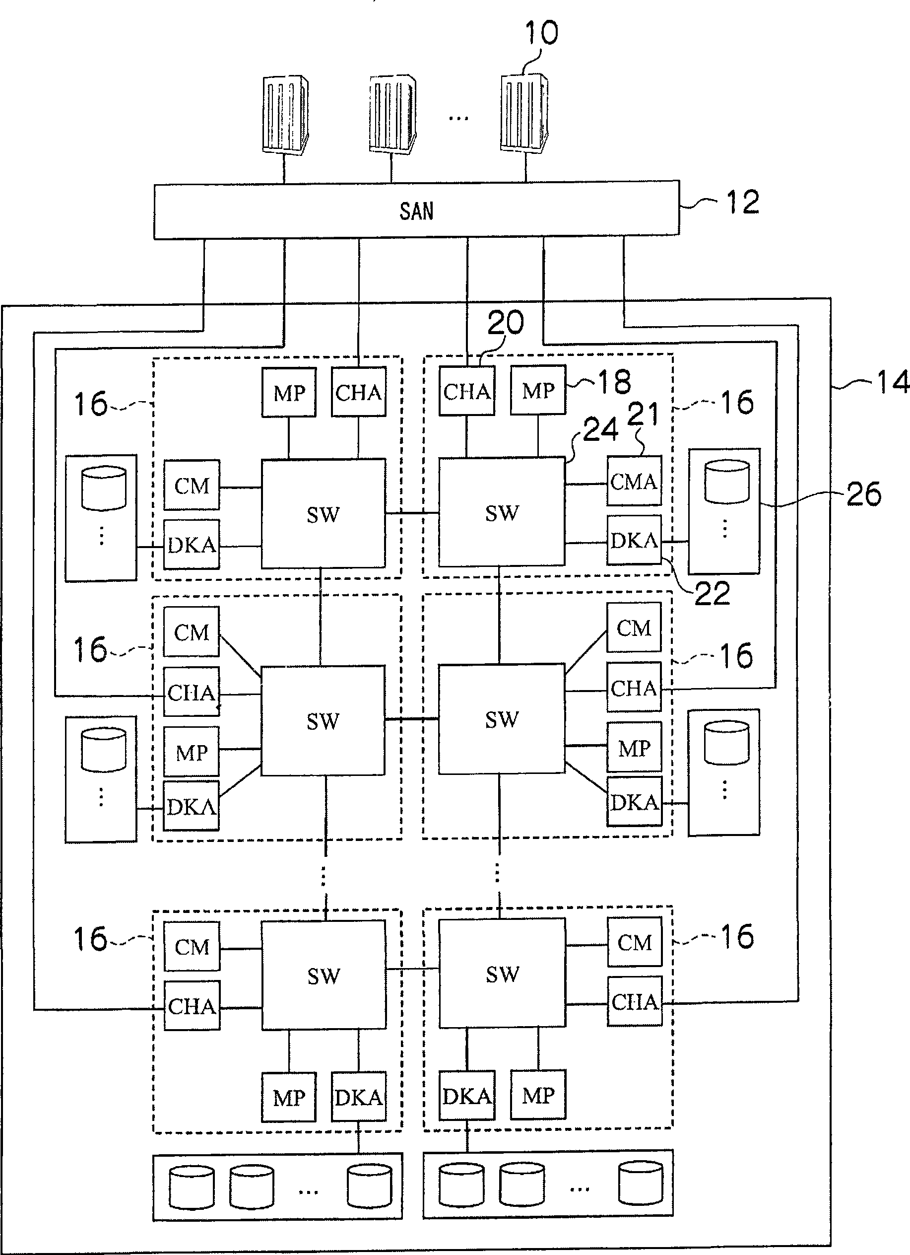
[0071] Next, embodiments of the present invention will be described. figure 1 is a block diagram of the storage system related to the present invention. This storage system has a configuration in which a plurality of host computers 10 are connected to a storage subsystem 14 via a SAN 12 as a network unit.

[0072] This storage subsystem 14 has a structure as a grid storage (Grid Storage). That is, the modules 16 can be sequentially added to the storage subsystem. The module 16 has multiple internal components such as storage resources and channel adapters that control data input and output for storage resources.

[0073] Each module 16 has: a channel adapter (CHA) 20, a microprocessor (MP) 18, a cache memory adapter (shown as CMA or CM in the figure) 21, a disk adapter (DKA) 22, a hard disk drive (HDD) as a storage resource ) and other storage devices (main storage device) 26, and switch adapter (SW) 24.

[0074] The channel adapter 20 controls data forwarding with the hos...


PUM


Abstract

Deadlock is avoided in a grid storage system having superior scalability. Provided is a storage subsystem connected to a host computer for receiving a write or read access from the host computer. This storage subsystem includes a plurality of modules respectively having a storage resource, a switch for connecting the plurality of modules, a controller for controlling the transfer of a packet based on the write or read access from the host computer to a target module among the plurality of modules via the switch, and a memory storing a transfer rule of the packet. The controller controls the transfer of the packet based on the transfer rule.

Description

technical field [0001] The present invention relates to a storage subsystem, and more particularly to a storage subsystem capable of suppressing deadlock in data packet communication in a network within the storage subsystem. Background technique [0002] There have been efforts to prevent deadlocks from occurring in computer systems. The so-called deadlock is a situation in which, in a communication network of a computer system, competition occurs in the processing of a plurality of data packets, causing the plurality of data packets to back off from each other, and the processing of the data packets cannot be performed. [0003] For example, JP-A-2002-344463 describes that, in a bidirectional ring network in which node devices connected to processing devices are connected in a ring through a link capable of bidirectional communication, in order to easily change data In the routing of packets, the node device has a cut-off point record register, and the cut-off point recor...

Claims


Application Information

Patent Timeline
Patent Type & Authority Applications(China)
IPC IPC(8): H04L12/56G06F3/06G06F12/00
CPCG06F3/0635H04L29/08549G06F3/067G06F3/0656G06F3/061H04L67/1097
Inventor 中村崇仁藤林昭细谷睦福田秀明
Owner HITACHI LTD
Learn More