Method, system and device for switching between APs
A handover request and handover condition technology, applied in transmission systems, digital transmission systems, data exchange networks, etc., can solve the problems of handover failure and inability to use handover procedures, and achieve the effect of reducing the burden
- Summary
- Abstract
- Description
- Claims
- Application Information
AI Technical Summary
Problems solved by technology
Method used
Image

Examples
Embodiment 1
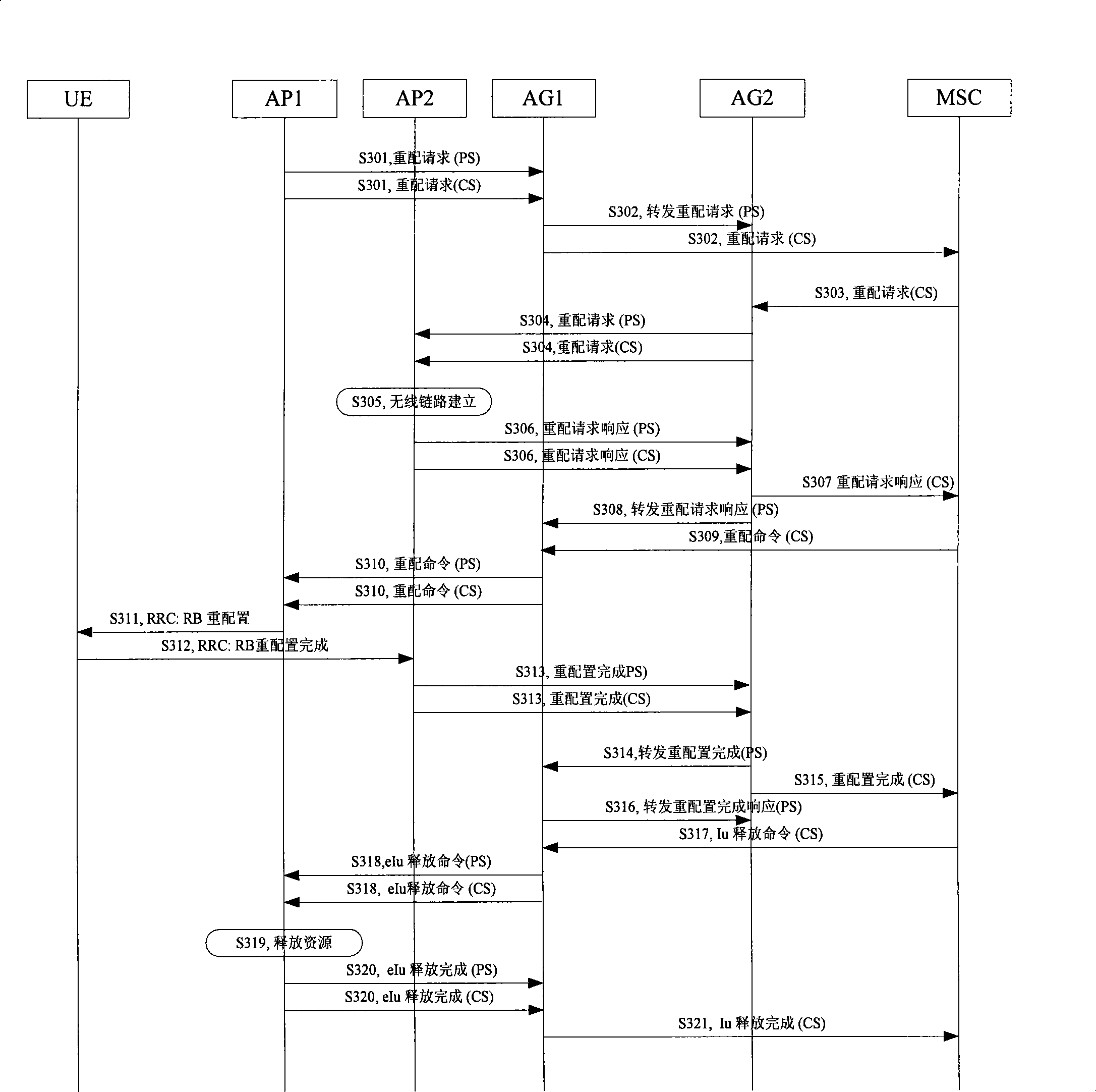
[0037] Such as Figure 4 As shown, it is a signaling flow chart of UE switching between AP1 and AP2 using the same RNC-ID in Embodiment 1 of the present invention. When the UE needs to switch from AP1 to AP2, through the switching process in Embodiment 1 of the present invention, After sending the UE parameters (including PS and CS context) on AP1 to AP2, AG adjusts the relevant tunnel path. Since the core network of the entire handover process in Embodiment 1 of the present invention is invisible, when AP1 and AP2 use the same RNC -ID and switchover avoids the problem that the existing core network MSC does not support switching between APs using the same RNC-ID. The specific steps are as follows:
[0038] Step S401: AP1 sends a handover request HandOver Required to AG;
[0039] The handover request carries the UE's PS and CS contexts, and through the handover request, AP1 sends the UE's PS and CS contexts to the AG.
[0040] In addition, after AP1 sends the handover reques...
Embodiment 2
[0068] Such as Figure 5 As shown, it is a flow chart of packaging PS and CS contexts into one signaling message to realize switching between AP1 and AP2 in Embodiment 2 of the present invention. Embodiment 2 of the present invention combines the user's PS and CS context messages into one UE parameter to switch between AP1 and AP2, which reduces the load on the AG to a certain extent and makes the switching process more efficient and stable. The steps are generally the same as those in Embodiment 1, and will not be repeated here.
[0069] In the second embodiment, the user's PS and CS contexts are mainly combined into one signaling for transmission, and the principle of transmission is basically the same as that of the first embodiment. Send it to AP2, and adjust the relevant parameters and tunnel direction on the AG at the same time. The core network of the process in the second embodiment is still invisible, and it can also be switched when the RNC-IDs of AP1 and AP2 are th...
Embodiment 3
[0071] Such as Figure 6 As shown, it is a flow chart of UE switching between AP1 and AP2 disclosed in Embodiment 3 of the present invention under the condition that AP1 and AP2 can communicate with each other. In this embodiment, since the signaling between AP1 and AP2 Can intercommunicate, AP1 can directly send UE parameters (including PS, CS context) to AP2, compared with the previous embodiment, this embodiment enables AG to receive fewer signaling messages, thereby further reducing the load of AG , which also makes the switching process easier and further improves the efficiency.
[0072] The intercommunication between AP1 and AP2 can be performed through the IP network between the APs, or through the Iur interface between the APs.
[0073] Specific steps are as follows:
[0074] Step S601, AP1 directly sends a Handover Request to AP2;
[0075] In step S602, AP2 makes a handover decision, and the specific decision method is generally the same as that of the foregoing e...
PUM
 Abstract
Description
Claims
Application Information
 - R&D
- Intellectual Property
- Life Sciences
- Materials
- Tech Scout
- Unparalleled Data Quality
- Higher Quality Content
- 60% Fewer Hallucinations
Browse by: Latest US Patents, China's latest patents, Technical Efficacy Thesaurus, Application Domain, Technology Topic, Popular Technical Reports.
© 2025 PatSnap. All rights reserved.Legal|Privacy policy|Modern Slavery Act Transparency Statement|Sitemap|About US| Contact US: help@patsnap.com